Shallow Thoughts : : hardware
Akkana's Musings on Open Source Computing and Technology, Science, and Nature.
Thu, 27 Feb 2020
![[Raspberry Pi automatic plant waterer]](http://shallowsky.com/blog/images/plantwater/img_3632cT.jpg) An automatic plant watering system is a
project that's been on my back burner for years.
I'd like to be able to go on vacation and not worry about
whatever houseplant I'm fruitlessly nursing at the moment.
(I have the opposite of a green thumb -- I have very little luck
growing plants -- but I keep trying, and if nothing else, I can
make sure lack of watering isn't the problem.)
An automatic plant watering system is a
project that's been on my back burner for years.
I'd like to be able to go on vacation and not worry about
whatever houseplant I'm fruitlessly nursing at the moment.
(I have the opposite of a green thumb -- I have very little luck
growing plants -- but I keep trying, and if nothing else, I can
make sure lack of watering isn't the problem.)
I've had all the parts sitting around for quite some time,
and had tried them all individually,
but never seemed to make the time to put them all together.
Today's "Raspberry Pi Jam" at Los Alamos Makers seemed like
the ideal excuse.
Sensing Soil Moisture
First step: the moisture sensor. I used a little moisture sensor that
I found on eBay. It says "YL-38" on it. It has the typical forked thingie
you stick into the soil, connected to a little sensor board.
The board has four pins: power, ground, analog and digital outputs.
The digital output would be the easiest: there's a potentiometer on
the board that you can turn to adjust sensitivity, then you can read
the digital output pin directly from the Raspberry Pi.
But I had bigger plans: in addition to watering, I wanted to
keep track of how fast the soil dries out, and update a
web page so that I could check my plant's status from anywhere.
For that, I needed to read the analog pin.
Raspberry Pis don't have a way to read an analog input.
(An Arduino would have made this easier, but then reporting to a
web page would have been much more difficult.)
So I used an ADS1115 16-bit I2sup>C Analog to Digital
Converter board from Adafruit, along with
Adafruit's
ADS1x15 library. It's written for CircuitPython, but it works
fine in normal Python on Raspbian.
It's simple to use. Wire power, ground, SDA and SDC to the appropriate
Raspberry Pi pins (1, 6, 3 and 5 respectively). Connect the soil
sensor's analog output pin with A0 on the ADC. Then
# Initialize the ADC
i2c = busio.I2C(board.SCL, board.SDA)
ads = ADS.ADS1015(i2c)
adc0 = AnalogIn(ads, ADS.P0)

# Read a value
value = adc0.value
voltage = adc0.voltage
With the probe stuck into dry soil, it read around 26,500 value, 3.3 volts.
Damp soil was more like 14528, 1.816V.
Suspended in water, it was more like 11,000 value, 1.3V.
Driving a Water Pump
The pump also came from eBay. They're under $5; search for terms like
"Mini Submersible Water Pump 5V to 12V DC Aquarium Fountain Pump Micro Pump".
As far as driving it is concerned, treat it as a motor. Which means you
can't drive it directly from a Raspberry Pi pin: they don't generate
enough current to run a motor, and you risk damaging the Pi with back-EMF
when the motor stops.
![[Raspberry Pi automatic plant waterer wiring]](http://shallowsky.com/blog/images/plantwater/plant-watering_bbT.jpg) Instead, my go-to motor driver for small microcontroller projects is
a SN754410 SN754410 H-bridge chip. I've used them before for
driving
little cars with a Raspberry Pi or
with
an Arduino. In this case the wiring would be much simpler, because
there's only one motor and I only need to drive it in one direction.
That means I could hardwire the two motor direction pins, and the
only pin I needed to control from the Pi was the PWM motor speed pin.
The chip also needs a bunch of ground wires (which it uses as heat
sinks), a line to logic voltage (the Pi's 3.3V pin) and motor voltage
(since it's such a tiny motor, I'm driving it from the Pi's 5v power pin).
Instead, my go-to motor driver for small microcontroller projects is
a SN754410 SN754410 H-bridge chip. I've used them before for
driving
little cars with a Raspberry Pi or
with
an Arduino. In this case the wiring would be much simpler, because
there's only one motor and I only need to drive it in one direction.
That means I could hardwire the two motor direction pins, and the
only pin I needed to control from the Pi was the PWM motor speed pin.
The chip also needs a bunch of ground wires (which it uses as heat
sinks), a line to logic voltage (the Pi's 3.3V pin) and motor voltage
(since it's such a tiny motor, I'm driving it from the Pi's 5v power pin).
Here's the full wiring diagram.
Driving a single PWM pin is a lot simpler than the dual bidirectional
motor controllers I've used in other motor projects.
GPIO.setmode(GPIO.BCM)
GPIO.setup(23, GPIO.OUT)
pump = GPIO.PWM(PUMP_PIN, 50)
pump.start(0)

# Run the motor at 30% for 2 seconds, then stop.
pump.ChangeDutyCycle(30)
time.sleep(2)
pump.ChangeDutyCycle(0)
The rest was just putting together some logic: check the sensor,
and if it's too dry, pump some water -- but only a little, then wait a
while for the water to soak in -- and repeat.
Here's the full
plantwater.py
script.
I haven't added the website part yet, but the basic plant waterer
is ready to use -- and ready to demo at tonight's Raspberry Pi Jam.
Tags: raspberry pi, programming, python
[
13:50 Feb 27, 2020
More hardware |
permalink to this entry |
]
Fri, 17 Aug 2018
Over the years I've picked up a couple of cellphone stands as
conference giveaways. A stand is a nice idea, especially if you
like to read news articles during mealtime, but the stands I've
tried never seem to be quite what I want. Either they're not
adjustable, or they're too bulky or heavy to want to carry them
around all the time.
A while back, I was browsing on ebay looking for something better
than the ones I have. I saw a few that looked like they might be
worth trying, but then it occurred to me: I could make one pretty
easily that would work better than anything I'd found for sale.
I started with plans that involved wire and a hinge -- the hinge so
the two sides of the stand would fold together to fit in a purse or
pocket -- and spent a few hours trying different hinge options.I
wasn't satisfied, though. And then I realized: all I had to do was
bend the wire into the shape I needed. Voilà -- instant
lightweight adjustable cellphone stand.
And it has worked great. I've been using it for months and it's much
better than any of the prefab stands I had before.
Bend a piece of wire
![[Bent wire]](http://shallowsky.com/blog/images/cellphone-stand/img_2635.jpg)
I don't know where this wire came from: it was in my spare-metal-parts
collection. You want something a little thinner than coathanger wire,
so you can bend it relatively easily; "baling wire" or "rebar wire"
is probably about right.
Bend the tips around
![[Tips adjusted to fit your phone's width]](http://shallowsky.com/blog/images/cellphone-stand/img_2638.jpg)
Adjust the curve so it's big enough that your cellphone will fit in
the crook of the wires.
Bend the back end down, and spread the two halves apart
![[Bend the back end down]](http://shallowsky.com/blog/images/cellphone-stand/img_2639.jpg)
Adjust so it fits your phone
![[Instant cellphone stand]](http://shallowsky.com/blog/images/cellphone-stand/img_2640.jpg)
Coat the finished stand with rubberized coating (available at
your local hardware store in either dip or spray-on varieties)
so it won't slide around on tables and won't scratch anything.
The finished product is adjustable to any angle you need -- so you
can adjust it based on the lighting in any room -- and you can fold
the two halves together to make it easy to carry.
Tags: hardware, hack
[
12:06 Aug 17, 2018
More hardware |
permalink to this entry |
]
Sat, 10 Mar 2018
![[Intel Galileo Gen2 by Mwilde2 on Wikimedia commons]](https://upload.wikimedia.org/wikipedia/commons/thumb/f/f8/IntelGalileoGen2.png/320px-IntelGalileoGen2.png) Our makerspace got a donation of a bunch of Galileo gen2 boards from Intel
(image
from Mwilde2
on Wikimedia commons).
Our makerspace got a donation of a bunch of Galileo gen2 boards from Intel
(image
from Mwilde2
on Wikimedia commons).
The Galileo line has been discontinued, so there's no support and
no community, but in theory they're fairly interesting boards.
You can use a Galileo in two ways: you can treat it
like an Arduino, after using the Arduino IDE to download a
Galileo hardware definition since they're not Atmega chips. They
even have Arduino-format headers so you can plug in an Arduino shield.
That works okay (once you figure out that you need to download
the Galileo v2 hardware definitions, not the regular Galileo).
But they run Linux under the hood, so you can also use them as a
single-board Linux computer.
Serial Cable
The first question is how to talk to the board. The documentation is terrible,
and web searches aren't much help because these boards were never
terribly popular. Worse, the v1 boards seem to have been more widely
adopted than the v2 boards, so a lot of what you find on the web
doesn't apply to v2. For instance, the v1 required a special serial cable
that used a headphone jack as its connector.
Some of the Intel documentation talks about how you can load a special
Arduino sketch that then disables the Arduino bootloader and instead
lets you use the USB cable as a serial monitor. That made me nervous:
once you load that sketch, Arduino mode no longer works until you
run a command on Linux to start it up again. So if the sketch doesn't
work, you may have no way to talk to the Galileo.
Given the state of the documentation I'd already struggled with for
Arduino mode, it didn't sound like a good gamble. I thought a real
serial cable sounded like a better option.
Of course, the Galileo documentation doesn't tell you what needs to
plug in where for a serial cable. The board does have a standard FTDI
6-pin header on the board next to the ethernet jack, and the labels on
the pins seemed to correspond to the standard pinout on my Adafruit
FTDI Friend: Gnd, CTS, VCC, TX, RX, RTS. So I tried that first, using
GNU screen to connect to it from Linux just like I would a Raspberry
Pi with a serial cable:
screen /dev/ttyUSB0 115200
Powered up the Galileo and sure enough, I got boot messages and was
able to log in as root with no password. It annoyingly forces orange
text on a black background, making it especially hard to read on
a light-background terminal, but hey, it's a start.
Later I tried a Raspberry Pi serial cable, with just RX (green), TX (white)
and Gnd (black) -- don't use the red VCC wire since the Galileo is already
getting power from its own power brick -- and that worked too. The Galileo
doesn't actually need CTS or RTS. So that's good: two easy ways to talk to
the board without buying specialized hardware. Funny they didn't bother
to mention it in the docs.
Blinking an LED from the Command Line
Once connected, how do you do anything? Most of the
Intel
tutorials on Linux are useless, devoting most of their space
to things like how to run Putty on Windows and no space at all to
how to talk to pins. But I finally found a
discussion thread
with a Python example for Galileo. That's not immediately helpful
since the built-in Linux doesn't have python installed (nor gcc,
natch). Fortunately, the Python example used files in /sys
rather than a dedicated Python library;
we can access /sys files just as well from the shell.
Of course, the first task is to blink an LED on pin 13. That
apparently corresponds to GPIO 7 (what are the other arduino/GPIO
correspondences? I haven't found a reference for that yet.) So you
need to export that pin (which creates /sys/class/gpio/gpio7
and set its direction to out. But that's not enough: the
pin still doesn't turn on when you
echo 1 > /sys/class/gpio/gpio7/value. Why not?
I don't know, but the Python script exports three other pins --
46, 30, and 31 -- and echoes 0 to 30 and 31. (It does this without
first setting their directions to out, and if you try
that, you'll get an error, so I'm not convinced the Python script
presented as the "Correct answer" would actually have worked. Be warned.)
Anyway, I ended up with these shell lines as
preparation before the Galileo can actually blink:
# echo 7 >/sys/class/gpio/export

# echo out > /sys/class/gpio/gpio7/direction

# echo 46 >/sys/class/gpio/export
# echo 30 >/sys/class/gpio/export
# echo 31 >/sys/class/gpio/export

# echo out > /sys/class/gpio/gpio30/direction
# echo out > /sys/class/gpio/gpio31/direction
# echo 0  > /sys/class/gpio/gpio30/value
# echo 0  > /sys/class/gpio/gpio31/value
And now, finally, you can control the LED on pin 13 (GPIO 7):
# echo 1 > /sys/class/gpio/gpio7/value
# echo 0 > /sys/class/gpio/gpio7/value
or run a blink loop:
# while /bin/true; do
> echo 1  > /sys/class/gpio/gpio7/value
> sleep 1
> echo 0  > /sys/class/gpio/gpio7/value
> sleep 1
> done
Searching Fruitlessly for a "Real" Linux Image
All the Galileo documentation is emphatic that you should download
a Linux distro and burn it to an SD card rather than using the Yocto
that comes preinstalled. The preinstalled Linux apparently has no
persistent storage, so not only does it not save your Linux programs,
it doesn't even remember the current Arduino sketch.
And it has no programming languages and only a rudimentary busybox shell.
So finding and downloading a Linux distro was the next step.
Unfortunately, that mostly led to dead ends. All the official Intel
docs describe different download filenames, and they all point to
generic download pages that no longer include any of the filenames
mentioned. Apparently Intel changed the name for its Galileo images
frequently and never updated its documentation.
After forty-five minutes of searching and clicking around,
I eventually found my way to
Intel® IoT Developer Kit Installer Files,
which includes sizable downloads with names like
- iss-iot-linux_12-09-16.tar.bz2 (324.07 MB),
- intel-iot-yocto.tar.xz (147.53 MB),
- intel-iot-wrs-pulsar-64.tar.xz (283.86 MB),
- intel-iot-wrs-32.tar.xz (386.16 MB), and
- intel-iot-ubuntu.tar.xz (209.44 MB)
From the size, I suspect those are all Linux images. But what are they
and how do they differ? Do any of them still have working repositories?
Which ones come with Python, with gcc, with GPIO support,
with useful development libraries? Do any of them get security updates?
As far as I can tell, the only way to tell is to download each image,
burn it to a card, boot from it, then explore the filesystem
trying to figure out what distro it is and how to try updating it.
But by this time I'd wasted three hours and gotten no
further than the shell commands to blink a single LED, and I ran out of
enthusiasm. I mean, I could spend five more hours on this, try several
of the Linux images, and see which one works best. Or I could spend
$10 on a Raspberry Pi Zero W that has abundant documentation,
libraries, books, and community howtos. Plus wi-fi, bluetooth and HDMI,
none of which the Galileo has.
Arduino and Linux Living Together
So that's as far as I've gone. But I do want to note
one useful thing I stumbled upon while searching
for information about Linux distributions:
Starting Arduino
sketch from Linux terminal shows how to run an Arduino sketch
(assuming it's already compiled) from Linux:
sketch.elf /dev/ttyGS0 &
It's a fairly cool option to have. Maybe one of these days, I'll pick
one of the many available distros and try it.
Tags: hardware, linux, intel, galileo, arduino
[
13:54 Mar 10, 2018
More hardware |
permalink to this entry |
]
Sat, 17 Feb 2018
In the previous article I talked about
Multiplexing
input/output using shift registers for a music keyboard project.
I ended up with three CD4021 8-bit shift registers cascaded.
It worked; but I found that I was spending all my time in the
delays between polling each bit serially. I wanted a way to read
those bits faster. So I ordered some I/O expander chips.
![[Keyboard wired to Raspberry Pi with two MCP23017 port expanders]](http://shallowsky.com/blog/images/multiplex/img_1995.jpg) I/O expander, or port expander, chips take a lot of the hassle out of
multiplexing. Instead of writing code to read bits serially, you can use I2C.
Some chips also have built-in pullup resistors, so you don't need all
those extra wires for pullups or pulldowns.
There are lots of options, but two common chips are the MCP23017,
which controls 16 lines, and the MCP23008 and PCF8574p, which each
handle 8. I'll only discuss the MCP23017 here, because if eight is good,
surely sixteen is better! But the MCP23008 is basically the same thing
with fewer I/O lines.
I/O expander, or port expander, chips take a lot of the hassle out of
multiplexing. Instead of writing code to read bits serially, you can use I2C.
Some chips also have built-in pullup resistors, so you don't need all
those extra wires for pullups or pulldowns.
There are lots of options, but two common chips are the MCP23017,
which controls 16 lines, and the MCP23008 and PCF8574p, which each
handle 8. I'll only discuss the MCP23017 here, because if eight is good,
surely sixteen is better! But the MCP23008 is basically the same thing
with fewer I/O lines.
A good tutorial to get you started is
How
To Use A MCP23017 I2C Port Expander With The Raspberry Pi - 2013 Part 1
along
with part
2, Python and
part
3, reading input.
I'm not going to try to repeat what's in those tutorials, just
fill in some gaps I found. For instance,
I didn't find I needed sudo for all those I2C commands in Part 1
since my user is already in the i2c group.
Using Python smbus
Part 2 of that tutorial uses Python smbus, but it doesn't really
explain all the magic numbers it uses, so it wasn't obvious how to
generalize it when I added a second expander chip. It uses this code:
DEVICE = 0x20 # Device address (A0-A2)
IODIRA = 0x00 # Pin direction register
OLATA  = 0x14 # Register for outputs
GPIOA  = 0x12 # Register for inputs

# Set all GPA pins as outputs by setting
# all bits of IODIRA register to 0
bus.write_byte_data(DEVICE,IODIRA,0x00)

# Set output all 7 output bits to 0
bus.write_byte_data(DEVICE,OLATA,0)
DEVICE is the address on the I2C bus, the one you see with
i2cdetect -y 1 (20, initially).
IODIRA is the direction: when you call
bus.write_byte_data(DEVICE, IODIRA, 0x00)
you're saying that all eight bits in GPA should be used for output.
Zero specifies output, one input: so if you said
bus.write_byte_data(DEVICE, IODIRA, 0x1F)
you'd be specifying that you want to use the lowest five bits for output
and the upper three for input.
OLATA = 0x14 is the command to use when writing data:
bus.write_byte_data(DEVICE, OLATA, MyData)
means write data to the eight GPA pins. But what if you want to write to
the eight GPB pins instead? Then you'd use
OLATB  = 0x15
bus.write_byte_data(DEVICE, OLATB, MyData)
Likewise, if you want to read input from some of the GPB bits, use
GPIOB  = 0x13
val = bus.read_byte_data(DEVICE, GPIOB)
The MCP23017 even has internal pullup resistors you can enable:
GPPUA  = 0x0c    # Pullup resistor on GPA
GPPUB  = 0x0d    # Pullup resistor on GPB
bus.write_byte_data(DEVICE, GPPUB, inmaskB)
Here's a full example:
MCP23017.py
on GitHub.
Using WiringPi
You can also talk to an MCP23017 using the WiringPi library.
In that case, you don't set all the bits at once, but instead treat
each bit as though it were a separate pin. That's easier to think
about conceptually -- you don't have to worry about bit shifting
and masking, just use pins one at a time -- but it might be slower
if the library is doing a separate read each time you ask for an input bit.
It's probably not the right approach to use if you're trying to check
a whole keyboard's state at once.
Start by picking a base address for the pin number -- 65 is the lowest
you can pick -- and initializing:
pin_base = 65
i2c_addr = 0x20

wiringpi.wiringPiSetup()
wiringpi.mcp23017Setup(pin_base, i2c_addr)
Then you can set input or output mode for each pin:
wiringpi.pinMode(pin_base, wiringpi.OUTPUT)
wiringpi.pinMode(input_pin, wiringpi.INPUT)
and then write to or read from each pin:
wiringpi.digitalWrite(pin_no, 1)
val = wiringpi.digitalRead(pin_no)
WiringPi also gives you access to the MCP23017's internal pullup resistors:
wiringpi.pullUpDnControl(input_pin, 2)
Here's an example in Python:
MCP23017-wiringpi.py
on GitHub, and one in C:
MCP23017-wiringpi.c
on GitHub.
Using multiple MCP23017s
But how do you cascade several MCP23017 chips?
Well, you don't actually cascade them. Since they're I2C
devices, you wire them so they each have different addresses on the
I2C bus, then query them individually. Happily, that's
easier than keeping track of how many bits you've looped through ona
shift register.
Pins 15, 16 and 17 on the chip are the address lines, labeled A0, A1
and A2. If you ground all three you get the base address of 0x20.
With all three connected to VCC, it will use 0x27 (binary 111 added to
the base address). So you can send commands to your first device at 0x20,
then to your second one at 0x21 and so on. If you're using WiringPi,
you can call mcp23017Setup(pin_base2, i2c_addr2) for your second chip.
I had trouble getting the addresses to work initially, and it turned
out the problem wasn't in my understanding of the address line wiring,
but that one of my cheap Chinese breadboard had a bad power and ground
bus in one quadrant. That's a good lesson for the future: when things
don't work as expected, don't assume the breadboard is above suspicion.
Using two MCP23017 chips with their built-in pullup resistors simplified
the wiring for my music keyboard enormously, and it made the code
cleaner too. Here's the modified code:
keyboard.py
on GitHub.
What about the speed? It is indeed quite a bit faster than the shift
register code. But it's still too laggy to use as a real music keyboard.
So I'll still need to do more profiling, and maybe find a faster way
of generating notes, if I want to play music on this toy.
Tags: hardware, raspberry pi, python
[
15:44 Feb 17, 2018
More hardware |
permalink to this entry |
]
Tue, 13 Feb 2018
I was scouting for parts at a thrift shop and spotted a little
23-key music keyboard. It looked like a fun Raspberry Pi project.
I was hoping it would turn out to use some common protocol like I2C,
but when I dissected it, it turned out there was a ribbon cable with
32 wires coming from the keyboard. So each key is a separate pushbutton.
![[23-key keyboard wired to a Raspberry Pi]](http://shallowsky.com/blog/images/multiplex/img_1986-640.jpg) A Raspberry Pi doesn't have that many GPIO pins, and neither does an
Arduino Uno. An Arduino Mega does, but buying a Mega to go between the
Pi and the keyboard kind of misses the point of scavenging a $3 keyboard;
I might as well just buy an I2C or MIDI keyboard. So I needed some sort
of I/O multiplexer that would let me read 31 keys using a lot fewer pins.
A Raspberry Pi doesn't have that many GPIO pins, and neither does an
Arduino Uno. An Arduino Mega does, but buying a Mega to go between the
Pi and the keyboard kind of misses the point of scavenging a $3 keyboard;
I might as well just buy an I2C or MIDI keyboard. So I needed some sort
of I/O multiplexer that would let me read 31 keys using a lot fewer pins.
There are a bunch of different approaches to multiplexing. A lot of
keyboards use a matrix approach, but that makes more sense when you're
wiring up all the buttons from scratch, not starting with a pre-wired
keyboard like this. The two approaches I'll discuss here are
shift registers and multiplexer chips.
If you just want to get the job done in the most efficient way,
you definitely want a multiplexer (port expander) chip, which I'll
cover in Part 2. But for now, let's look at the old-school way: shift
registers.
PISO Shift Registers
There are lots of types of shift registers, but for reading lots of inputs,
you need a PISO shift register: "Parallel In, Serial Out."
That means you can tell the chip to read some number -- typically 8 --
of inputs in parallel, then switch into serial mode and read all the bits
one at a time.
Some PISO shift registers can cascade: you can connect a second shift
register to the first one and read twice as many bits. For 23 keys
I needed three 8-bit shift registers.
Two popular cascading PISO shift registers are the CD4021 and the SN74LS165.
They work similarly but they're not exactly the same.
The basic principle with both the CD4021 and the SN74LS165:
connect power and ground, and wire up all your inputs to the eight data pins.
You'll need pullup or pulldown resistors on each input line, just like
you normally would for a pushbutton; I recommend picking up a few
high-value (like 1-10k) resistor arrays: you can get these in SIP
(single inline package) or DIP (dual-) form factors that plug easily
into a breadboard. Resistor arrays can be either independent
two pins for each resistor in the array) or bussed (one pin in
the chip is a common pin, which you wire to ground for a pulldown or
V+ for a pullup; each of the rest of the pins is a resistor). I find
bussed networks particularly handy because they can reduce the number
of wires you need to run, and with a job where you're multiplexing
lots of lines, you'll find that getting the wiring straight is a big
part of the job. (See the photo above to see what a snarl this was
even with resistor networks.)
For the CD4021, connect three more pins: clock and data pins (labeled
CLK and either Q7 or Q8 on the chip's pinout, pins 10 and 3),
plus a "latch" pin (labeled M, pin 9).
For the SN74LS165, you need one more pin: you need clock and data
(labeled CP and Q7, pins 2 and 9), latch (labeled
PL, pin 1),
and clock enable (labeled CE,
pin 15).
At least for the CD4021, some people
recommend
a 0.1 uF bypass capacitor across the power/ground connections of each
CD4021.
If you need to cascade several chips with the CD4021, wire DS (pin 11)
from the first chip to Q7 (pin 3), then wire both chips clock lines together
and both chips' data lines together. The SN74LS165 is the same: DS
(pin 10) to Q8 (pin 9) and tie the clock and data lines together.
Once wired up, you toggle the latch to read the parallel data, then
toggle it again and use the clock pin to read the series of bits.
You can see the specific details in my Python scripts:
CD4021.py
on GitHub and
SN74LS165.py
on GitHub.
Some References
For wiring diagrams, more background, and Arduino code for the CD4021, read
Arduino
ShiftIn.
For the SN74LS165, read:
Arduino:
SN74HC165N,
74HC165 8 bit Parallel in/Serial out Shift Register,
or Sparkfun:
Shift Registers.
Of course, you can use a shift register for output as well as input.
In that case you need a SIPO (Serial In, Parallel Out) shift register
like a 74HC595. See
Arduino ShiftOut:
Serial to Parallel Shifting-Out with a 74HC595
Interfacing
74HC595 Serial Shift Register with Raspberry Pi.
Another, less common option is the 74HC164N:
Using
a SN74HC164N Shift Register With Raspberry Pi
For input from my keyboard, initially I used three CD4021s. It basically worked,
and you can see the code for it at
keyboard.py
(older version, for CD4021 shift registers), on GitHub.
But it turned out that looping over all those bits was slow -- I've
been advised that you should wait at least 25 microseconds between
bits for the CD4021, and even at 10 microseconds I found there wasa
significant delay between hitting the key and hearing the note.I
thought it might be all the fancy numpy code to generate waveforms for
the chords, but when I used the Python profiler, it said most of the
program's time was taken up in time.sleep(). Fortunately, there's a
faster solution than shift registers: port expanders, which I'll talk
about in Multiplexing Part 2: Port Expanders.
Tags: hardware, raspberry pi, python
[
12:23 Feb 13, 2018
More hardware |
permalink to this entry |
]
Sun, 21 Jan 2018
When you attach hardware buttons to a Raspberry Pi's GPIO pin,
reading the button's value at any given instant is easy with
GPIO.input(). But what if you want to watch for
button changes? And how do you do that from a GUI program where
the main loop is buried in some library?
Here are some examples of ways to read buttons from a Pi.
For this example, I have one side of my button wired to the Raspberry
Pi's GPIO 18 and the other side wired to the Pi's 3.3v pin.
I'll use the Pi's internal pulldown resistor rather than adding
external resistors.
The simplest way: Polling
The obvious way to monitor a button is in a loop, checking the
button's value each time:
import RPi.GPIO as GPIO
import time

button_pin = 18

GPIO.setmode(GPIO.BCM)

GPIO.setup(button_pin, GPIO.IN, pull_up_down = GPIO.PUD_DOWN)

try:
    while True:
        if GPIO.input(button_pin):
            print("ON")
        else:
            print("OFF")

        time.sleep(1)

except KeyboardInterrupt:
    print("Cleaning up")
    GPIO.cleanup()
But if you want to be doing something else while you're waiting,
instead of just sleeping for a second, it's better to use edge detection.
Edge Detection
GPIO.add_event_detect,
will call you back whenever it sees the pin's value change.
I'll define a button_handler function that prints out
the value of the pin whenever it gets called:
import RPi.GPIO as GPIO
import time

def button_handler(pin):
    print("pin %s's value is %s" % (pin, GPIO.input(pin)))

if __name__ == '__main__':
    button_pin = 18

    GPIO.setmode(GPIO.BCM)

    GPIO.setup(button_pin, GPIO.IN, pull_up_down = GPIO.PUD_DOWN)

    # events can be GPIO.RISING, GPIO.FALLING, or GPIO.BOTH
    GPIO.add_event_detect(button_pin, GPIO.BOTH,
                          callback=button_handler,
                          bouncetime=300)

    try:
        time.sleep(1000)
    except KeyboardInterrupt:
        GPIO.cleanup()
Pretty nifty. But if you try it, you'll probably find that sometimes
the value is wrong. You release the switch but it says the value is
1 rather than 0. What's up?
Debounce and Delays
The problem seems to be in the way RPi.GPIO handles that
bouncetime=300 parameter.
The bouncetime is there because hardware switches are noisy. As you
move the switch from ON to OFF, it doesn't go cleanly all at once
from 3.3 volts to 0 volts. Most switches will flicker back
and forth between the two values before settling down. To see bounce
in action, try the program above without the bouncetime=300.
There are ways of fixing bounce in hardware, by adding a capacitor or
a Schmitt trigger to the circuit; or you can "debounce" the button
in software, by waiting a while after you see a change before
acting on it. That's what the bouncetime parameter is for.
But apparently RPi.GPIO, when it handles bouncetime, doesn't
always wait quite long enough before calling its event function.
It sometimes calls button_handler while the switch is still
bouncing, and the value you read might be the wrong one.
Increasing bouncetime doesn't help.
This seems to be a bug in the RPi.GPIO library.
You'll get more reliable results if you wait a little while before
reading the pin's value:
def button_handler(pin):
    time.sleep(.01)    # Wait a while for the pin to settle
    print("pin %s's value is %s" % (pin, GPIO.input(pin)))
Why .01 seconds? Because when I tried it, .001 wasn't enough, and if
I used the full bounce time, .3 seconds (corresponding to 300 millisecond
bouncetime), I found that the button handler
sometimes got called multiple times with the wrong value. I wish
I had a better answer for the right amount of time to wait.
Incidentally, the choice of 300 milliseconds for bouncetime is arbitrary
and the best value depends on the circuit. You can play around with
different values (after commenting out the .01-second sleep) and
see how they work with your own circuit and switch.
You might think you could solve the problem by using two handlers:
    GPIO.add_event_detect(button_pin, GPIO.RISING, callback=button_on,
                          bouncetime=bouncetime)
    GPIO.add_event_detect(button_pin, GPIO.FALLING, callback=button_off,
                          bouncetime=bouncetime)
but that apparently isn't allowed:
RuntimeError: Conflicting edge detection already enabled for
this GPIO channel
.
Even if you look just for GPIO.RISING, you'll
still get some bogus calls, because there are both rising and falling
edges as the switch bounces. Detecting GPIO.BOTH, waiting
a short time and checking the pin's value is the only reliable method
I've found.
Edge Detection from a GUI Program
And now, the main inspiration for all of this: when you're running a
program with a graphical user interface, you don't have
control over the event loop. Fortunately, edge detection works
fine from a GUI program. For instance, here's a simple TkInter program
that monitors a button and shows its state.
import Tkinter
from RPi import GPIO
import time

class ButtonWindow:
    def __init__(self, button_pin):
        self.tkroot = Tkinter.Tk()
        self.tkroot.geometry("100x60")

        self.label = Tkinter.Label(self.tkroot, text="????",
                                   bg="black", fg="white")
        self.label.pack(padx=5, pady=10, side=Tkinter.LEFT)

        self.button_pin = button_pin
        GPIO.setmode(GPIO.BCM)

        GPIO.setup(self.button_pin, GPIO.IN, pull_up_down=GPIO.PUD_DOWN)

        GPIO.add_event_detect(self.button_pin, GPIO.BOTH,
                              callback=self.button_handler,
                              bouncetime=300)

    def button_handler(self, channel):
        time.sleep(.01)
        if GPIO.input(channel):
            self.label.config(text="ON")
            self.label.configure(bg="red")
        else:
            self.label.config(text="OFF")
            self.label.configure(bg="blue")

if __name__ == '__main__':
    win = ButtonWindow(18)
    win.tkroot.mainloop()
You can see slightly longer versions of these programs in my
GitHub
Pi Zero Book repository.
Tags: hardware, raspberry pi, programming, python
[
11:32 Jan 21, 2018
More hardware |
permalink to this entry |
]
Sat, 16 Dec 2017
Playing with the
ATtiny85
I was struck by how simple the circuit was.
Sure, I'd made a
homemade
Arduino on a breadboard;
but with the crystal and all the extra capacitors and resistors it ends
up seeming like a lot of parts and wires.
If an ATtiny can use a built-in clock and not need all those extra
parts, couldn't I use an Atmega328 the same way?
![[Circuit for Atmega328 on breadboard with ISP]](http://shallowsky.com/blog/images/arduino/bare-atmega-breadboard-isp_bb.jpg) Why, yes, as it turns out. But there are a few tricks.
Why, yes, as it turns out. But there are a few tricks.
Wire it
Wiring a bare Atmega chip is easy.
You'll want to keep a good pinout diagram handy, like this
Arduino
ATmega328 Pinout from HobbyTronics.
For the initial wiring, all you need is
two power and two ground lines, the pins marked - and +,
plus a pullup resistor on RST (something large, like 10kΩ).
The excellent tutorial
From
Arduino to a Microcontroller on a Breadboard is a good guide
if you need additional details: the third section
shows a circuit without external clock.
Add an LED and resistor on pin 13 (atmega pin 19, called SCK) so
you can test it using a blink program.
Now you need to set up the software.
Set up a hardware profile for a bare Arduino
To program it with the Arduino libraries,
you'll need a hardware definition for an atmega328 chip
with an internal clock. I used the download
from the last section of the excellent tutorial,
From
Arduino to a Microcontroller on a Breadboard. (Keep that page
up: it has good wiring diagrams.)
For Arduino 1.8.5, download breadboard-1-6-x.zip and unpack it
in your ~/sketchbook/hardware/ directory, making a directory
there called breadboard. Then you'll need to make one change:
the 1.6 directory is missing a file called pins_arduino.h",
so if you try to compile with this hardware definition, you'll get
an error like:
mkdir -p build-atmega328bb-atmega328
/usr/local/share/arduino/hardware/tools/avr/bin/avr-g++ -x c++ -include Arduino.h -MMD -c -mmcu=atmega328p -DF_CPU=8000000L -DARDUINO=185 -DARDUINO_ARCH_AVR -D__PROG_TYPES_COMPAT__ -I/usr/local/share/arduino/hardware/arduino/avr/cores/arduino -I/home/akkana/sketchbook/hardware/breadboard/avr/variants/standard    -Wall -ffunction-sections -fdata-sections -Os -fpermissive -fno-exceptions -std=gnu++11 -fno-threadsafe-statics -flto blink.ino -o build-atmega328bb-atmega328/blink.ino.o
In file included from :0:0:
/usr/local/share/arduino/hardware/arduino/avr/cores/arduino/Arduino.h:257:26: fatal error: pins_arduino.h: No such file or directory
 #include "pins_arduino.h"
                          ^
compilation terminated.
/usr/share/arduino/Arduino.mk:1251: recipe for target 'build-atmega328bb-atmega328/blink.ino.o' failed
make: *** [build-atmega328bb-atmega328/blink.ino.o] Error 1
The problem is that it's including these directories:
-I/usr/local/share/arduino/hardware/arduino/avr/cores/arduino
 -I/home/akkana/sketchbook/hardware/breadboard/avr/variants/standard
but the actual file is in:
/usr/local/share/arduino/hardware/arduino/avr/variants/standard/pins_arduino.h
You can fix that by making a link from the "standard" directory in your
Arduino install to breadboard/avr/variants/standard. On Linux, that would
be something like this (Mac and Windows people can substitute their
local equivalents):
ln -s /usr/local/share/arduino/hardware/arduino/avr/variants/standard ~/sketchbook/hardware/breadboard/avr/variants/
Now your hardware definition should be ready to go. To check, fire up
the IDE and look in Tools->Board for
ATmega328 on a breadboard (8 MHz internal clock).
Or if you use Arduino-mk, run
ALTERNATE_CORE=breadboard make show_boards
and make sure it lists
atmega328bb ATmega328 on a breadboard (8 MHz internal clock).
Reprogram the Fuses and Bootloader for an Internal Clock
The next trick is that an Atmega chip programmed with the Arduino
bootloader is also fused to use an external, 16MHz clock.
If you wire it to use its internal 8MHz clock, you won't be
able to talk to it with either an ISP or FTDI.
You'll definitely run into this if you pull the CPU out of an Arduino.
But even if you buy new chips you may see it:
many Atmega328s come pre-programmed with the Arduino bootloader.
After all, that's what most people want.
The easiest way to reprogram the fuses is to use the hardware
definition you just installed to burn a new bootloader, which resets
the fuse settings at the same time. So you need an In-System
Programmer, or ISP. You can use an Arduino as an ISP, but I'm told
that this tends to be flaky and isn't recommended. After I had
problems using an Arduino I ordered a cheap USBtinyUSP, which works
fine.
Regardless of which ISP you use, if you wire up your atmega without
an external clock when it's fused for one, you won't be able to burn a
bootloader. A typical error:
[ ... ]
Reading | ################################################## | 100% 0.02s

avrdude: Device signature = 0x000000 (retrying)

Error while burning bootloader.
Reading | ################################################## | 100% 0.02s

avrdude: Device signature = 0x000000
avrdude: Yikes!  Invalid device signature.
     Double check connections and try again, or use -F to override
     this check.
The solution is to burn the bootloader using an external clock.
You can add a crystal and two capacitors to your breadboard circuit
if you have them.
If not, an easy solution is to pull the chip out of the breadboard,
plug it into the socket in an Arduino and burn it there.
(Note: if you're using an Arduino as your ISP, you'll need a second
Arduino.)
Plug your ISP into the Arduino's ISP header: on an Uno, that's the
header labeled ICSP at the end of the chip farthest away from the USB
plug. It's a six-pin connector (2x3), it's easy to plug in backward
and you can't depend on either the Arduino's header or the ISP's cable
being labeled as to direction; if in doubt, use a multimeter in
continuity mode to see which pin is ground on each side, then make
sure those pins match. Once you're sure, mark your connector somehow
so you'll know next time.
In the Arduino IDE, set Tools->Board to
ATmega328 on a breadboard (8 MHz internal clock),
set Programmer to whatever ISP you're using.
then run Tools->Burn Bootloader.
If you're using Arduino-mk instead of the IDE,
set up a Makefile that looks like this:
ALTERNATE_CORE = breadboard
BOARD_TAG      = atmega328bb
ISP_PROG     = usbtiny
include /usr/local/share/Arduino-Makefile/Arduino.mk
Substitute your ISP, if different, and your location for Arduino.mk.
Then type
make burn_bootloader
Program it
Once you're wired, you should be able to program it either with an
FTDI board or an ISP, as I discussed in
homemade
Arduino, Part 1.
You should be able to use your minimal Atmega328 to
run anything you can run on a normal Arduino (albeit at half the
clock speed).
I plan to make a little board with a ZIF socket and connectors for
both the USBtinyISP and the FTDI Friend so I don't have to plug in
all those wires again each time.
Tags: hardware, arduino
[
13:14 Dec 16, 2017
More hardware |
permalink to this entry |
]
Sat, 09 Dec 2017
There are lots of tutorials around for building an Arduino on a
breadboard, using an Atmega328 (or the older 168) chip, a crystal,
a few capacitors and resistors and a power supply.
It's a fun project that every Arduino hacker should try at least once.
But while there are lots of instructions on how to wire up a breadboard
Arduino, most instructions on how to program one are confusing and incomplete.
Of course, you can program your Atmega chip while it's in an Arduino,
then unplug it from the Arduino's socket and move it to the
breadboard. But what a hassle! It's so more convenient to leave the chip
in the breadboard while you test new versions of the code. And you can,
in two different ways: with FTDI, which uses the Arduino bootloader,
or with an ISP, which doesn't.
Either way, start by downloading a good pinout diagram for the
Atmega328 chip. I use this one: the
Arduino
ATmega328 Pinout from HobbyTronics, which is very compact yet does a
good job of including both the mappings to Arduino digital and analog
pins and the functions like RX, TX, MOSI and MISO you'll need for
programming the chip.
Load Programs with FTDI
![[Circuit for Atmega328 on breadboard with FTDI friend]](http://shallowsky.com/blog/images/arduino/bare-atmega-breadboard-ftdi_bb.jpg) An FTDI board is a little trickier to wire than an ISP, but it's
less risky because it loads the code the same way an Arduino would,
so you don't overwrite the bootloader and you
can still put your chip back into an Arduino if things go wrong.
So let's start with FTDI.
An FTDI board is a little trickier to wire than an ISP, but it's
less risky because it loads the code the same way an Arduino would,
so you don't overwrite the bootloader and you
can still put your chip back into an Arduino if things go wrong.
So let's start with FTDI.
I use an
Adafruit "FTDI Friend", but there are lots of similar
FTDI boards from Sparkfun
and other vendors. They have six outputs,
but you'll need only five of those. Referring to your Atmega pinout,
wire up power, ground, TX, and RX. For some FTDI boards you may need
pullup resistors on the TX and RX lines; I didn't need them.
Now you have four pins connected.
Wiring the reset line is more complicated because it requires a
0.1μF capacitor. A lot of tutorials don't mention the capacitor,
but it didn't work for me without one.
Connect from RTS on the FTDI board, through the
0.1μF cap, to the RST line.
A 0.1μF capacitor is an electrolytic cap with a positive and a
negative lead, but the few online tutorials that even mention the
capacitor don't bother to say which side is whick. I connected the
FTDI friend to the cap's negative lead, and the positive lead to the
Atmega chip, and it worked.
You may also need a pullup on that RST/RTS line: a resistor
around 10kΩ from the RST pin 1 of the atmega chip to the 5v power line.
Note: the Fritzing diagram here shows pullup resistors on RST, TX
and RX. You may not need any of them.
Incidentally, RST stands for "reset", while RTS stands for "Ready To
Send"; they're not meant as anagrams of each other. The remaining pin
on the FTDI friend, CTS, is "Clear To Send" and isn't needed for an
Arduino.
Once the wiring is ready, plug in the FTDI board, check to make sure
Port is set to whatever port the FTDI board registered,
and try uploading a program as if you were uploading to a normal Arduino Uno.
And cross your fingers. If it doesn't work, try fiddling with pullups
and capacitor values.
Load Programs with an ISP
An In-System Programmer, or ISP, writes programs straight to the chip,
bypassing (and overwriting) the Arduino bootloader. You can also use
an ISP to burn a new bootloader and reprogram the fuses on your
Arduino, to change parameters like the clock rate. (More on that in Part 2.)
You can use an
Arduino as an ISP, but it's somewhat unreliable and
prone to unexplained errors. A dedicated ISP isn't expensive, is
easier to wire and is more likely to work. A common type of ISP is
called a "USBtinyISP", and you can buy one from vendors like
Sparkfun or
Adafruit,
or search for usbtinyisp on sites like ebay or aliexpress.
Update: I've been curious about this flakiness: why does "Arduino as ISP"
work fine for some people and utterly fail for others? One person I asked
thought it had to do with the way Arduinos reset the RESET line whenever
the serial port is opened: so RESET gets toggled at the wrong time as
the bootloader code is being transferred.
An alternate method that may get around this is
Gammon Forum's
Atmega bootloader programmer, which includes the bootloader bits
as part of the code so it doesn't need to re-open the serial port.
Someone else says a 10 uF capacitor between reset and ground should
prevent that from happening; and another person says it should be a
100nF capacitor between RST on the programmer and RST on the AVR-chip
plus a 10k pullup resistor,
Most Arduino-as-ISP tutorials, including the official ones on arduino.cc,
don't mention either capacitors or pullups,
so that may explain why the method works for some people and not others.
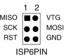 ISPs typically use a six-pin connector (2x3). It's not always easy to
figure out which end is which, so use a multimeter in continuity mode
to figure out which pin is ground. Once you're sure, mark your connector
so you'll know which pin is pin 1 (MISO, the pin opposite ground).
ISPs typically use a six-pin connector (2x3). It's not always easy to
figure out which end is which, so use a multimeter in continuity mode
to figure out which pin is ground. Once you're sure, mark your connector
so you'll know which pin is pin 1 (MISO, the pin opposite ground).
Once you have your ISP pins straight, refer to your handy-dandy
Atmega328 pinout and connect power, ground, MOSI, MISO, SCK, and RST
to the appropriate Atmega pins.
All wired up? In the Arduino IDE, set Programmer to your ISP,
for instance, USBtinyISP or Arduino as ISP
Then use the Upload button to upload sketches.
If you prefer Arduino-mk instead of the IDE, add this to your Makefile:
ISP_PROG = usbtiny
(or whatever ISP you're using). Then type
make ispload
instead of
make upload
Once you have your FTDI or ISP working, then you can think about making
an even simpler circuit -- without the external clock and its associated
capacitors. But there are a couple of additional tricks to that.
Stay tuned for Part 2.
Tags: hardware, arduino
[
15:44 Dec 09, 2017
More hardware |
permalink to this entry |
]
![[Raspberry Pi automatic plant waterer]](http://shallowsky.com/blog/images/plantwater/img_3632c.jpg) An automatic plant watering system is a
project that's been on my back burner for years.
I'd like to be able to go on vacation and not worry about
whatever houseplant I'm fruitlessly nursing at the moment.
(I have the opposite of a green thumb -- I have very little luck
growing plants -- but I keep trying, and if nothing else, I can
make sure lack of watering isn't the problem.)
An automatic plant watering system is a
project that's been on my back burner for years.
I'd like to be able to go on vacation and not worry about
whatever houseplant I'm fruitlessly nursing at the moment.
(I have the opposite of a green thumb -- I have very little luck
growing plants -- but I keep trying, and if nothing else, I can
make sure lack of watering isn't the problem.)
![[Raspberry Pi automatic plant waterer wiring]](http://shallowsky.com/blog/images/plantwater/plant-watering_bb.jpg) Instead, my go-to motor driver for small microcontroller projects is
a SN754410 SN754410 H-bridge chip. I've used them before for
driving
little cars with a Raspberry Pi or
with
an Arduino. In this case the wiring would be much simpler, because
there's only one motor and I only need to drive it in one direction.
That means I could hardwire the two motor direction pins, and the
only pin I needed to control from the Pi was the PWM motor speed pin.
The chip also needs a bunch of ground wires (which it uses as heat
sinks), a line to logic voltage (the Pi's 3.3V pin) and motor voltage
(since it's such a tiny motor, I'm driving it from the Pi's 5v power pin).
Instead, my go-to motor driver for small microcontroller projects is
a SN754410 SN754410 H-bridge chip. I've used them before for
driving
little cars with a Raspberry Pi or
with
an Arduino. In this case the wiring would be much simpler, because
there's only one motor and I only need to drive it in one direction.
That means I could hardwire the two motor direction pins, and the
only pin I needed to control from the Pi was the PWM motor speed pin.
The chip also needs a bunch of ground wires (which it uses as heat
sinks), a line to logic voltage (the Pi's 3.3V pin) and motor voltage
(since it's such a tiny motor, I'm driving it from the Pi's 5v power pin).