Shallow Thoughts : tags : beaglebone
Akkana's Musings on Open Source Computing and Technology, Science, and Nature.
Sun, 11 Aug 2013
Want to get started controlling hardware from your BeagleBone Black?
I've found a lot of the documentation and tutorials a little sketchy,
so here's what I hope is a quick start guide.
I used the
Adafruit
Python GPIO library for my initial hacking.
It's easy to set up:
once you have your network set up, run these commands:
opkg update && opkg install python-pip python-setuptools python-smbus
pip install Adafruit_BBIO
Pinout diagrams
First, where can you plug things in? The BBB has two huge header blocks,
P8 and P9,
but trying to find pinout diagrams for them is a problem. Don't blindly
trust any diagram you find on the net; compare it against several
others, and you may find there are big differences. I've found a
lot of mislabeled BBB diagrams out there.
The best I've found so far are the two tables at
elinux.org/BeagleBone.
No pictures, but the tables are fairly readable and seem to be
correct.
The
official
BeagleBone Black hardware manual is the reference you're actually
supposed to use.
It's a 121-page PDF full of incomprehensible and unexplained abbreviations.
Good luck! The pin tables for P8 and P9 are on pp. 80 and 82.
P8 and P8 are identified on p. 78.
Blinking an LED: basic GPIO output
For basic GPIO output, you have a wide choice of pins.
Use the tables to identify power and ground, then pick a GPIO pin
that doesn't seem to have too many other uses.
The Adafruit library can identify pins either by their location
on the P8 and P9 headers, e.g. "P9_11", or by GPIO number, e.g.
"GPIO0_26". Except -- with the latter designation, what's that extra
zero between GPIO and _26? Is it always 0? Adafruit doesn't explain it.
So for now I'm sticking to the PN_NN format.
I plugged my LED and resistor into ground (there are lots of ground
terminals -- I used pin 0 on the P9 header) and pin 11 on P9.
It's one line to enable it, and then you can turn it on and off:
import Adafruit_BBIO.GPIO as GPIO

GPIO.setup("P9_11", GPIO.OUT)
GPIO.output("P9_11", GPIO.HIGH)
GPIO.output("P9_11", GPIO.LOW)
GPIO.output("P9_11", GPIO.HIGH)
Or make it blink:
import time
while True:
    GPIO.output("P9_11", GPIO.HIGH)
    time.sleep(.5)
    GPIO.output("P9_11", GPIO.LOW)
    time.sleep(.5)
Fading an LED: PWM output
PWM is harder. Mostly because it's not easy to find out which pins
can be used for GPIO. All the promotional literature on the BBB says
it has 8 GPIO outputs -- but which ones are those?
If you spend half an hour searching for "pwm" in that long PDF manual
and collecting a list of pins with "pwm" in their description,
you'll find 13 of them on P9 and 12 on P8. So that's no help.
After comparing a bunch of references and cross-checking pin numbers
against the descriptions in the hardware manual, I think this is the list:
P9_14 P9_16 P9_21 P9_22 P9_28 P9_31
P8_13 P8_19
I haven't actually verified all of them yet, though.
Once you've found a pin that works for PWM, the rest is easy.
Start it and set an initial frequency with PWM.start(pin, freq),
and then you can change the duty cycle with set_duty_cycle(pin, cycle)
where cycle is a number between 0 and 100. The duty cycle
is the reverse of what you might expect: if you have an LED plugged
in, a duty cycle of 0 will be brightest, 100 will be dimmest.
You can also change the frequency with PWM.set_frequency(pin, freq).
I'm guessing freq is in Hertz, but they don't actually say.
When you're done, you should call PWM.stop() and PWM.cleanup().
Here's how to fade an LED from dim to bright ten times:
import Adafruit_BBIO.PWM as PWM

PWM.start("P9_14", 50)

for j in range(10):
    for i in range(100, 0, -1):
        PWM.set_duty_cycle("P9_14", i)
        time.sleep(.02)

PWM.stop("P9_14")
PWM.cleanup()
Tags: hardware, linux, beaglebone, maker
[
13:36 Aug 11, 2013
More hardware |
permalink to this entry |
]
Tue, 16 Jul 2013
Just a couple of tips for communicating with your BeagleBone Black
once you have it flashed with the latest Angstrom:
Configure the USB network
The Beaglebone Black running Angstrom has a wonderful feature:
when it's connected to your desktop via the mini USB cable, you
can not only mount it like a disk, but you can also set up networking
to it.
If the desktop is running Linux, you should have all the drivers you need.
But you might need a couple of udev rules to make the network device
show up. I ran the
mkudevrule.sh
from the official Getting Started page, which creates four rules
and then runs sudo udevadm control --reload-rules to enable them
without needing to reboot your Linux machine.
Now you're ready to boot the BeagleBone Black running Angstrom.
Ideally you'll want it connected to your desktop machine by
the mini USB cable, but also plugged in to a separate power supply.
Your Linux machine should see it as a new network device, probably
eth1: run ifconfig -a to see it.
The Beagle is already configured as 192.168.7.2. So you can talk
to it by configuring your desktop machine to be .1 on the same network:
ifconfig eth1 192.168.7.1
So now you can ssh from your desktop machine to the BBB,
or point your browser at the BBB's built in web pages.
Make your Linux machine a router for the Beaglebone
If you want the Beaglebone Black to have access to the net, there are
two more things you need to do.
First, on the BBB itself, run these two lines:
/sbin/route add default gw 192.168.7.1
echo "nameserver 8.8.8.8" >> /etc/resolv.conf
You'll probably want to add these lines to the end of
/usr/bin/g-ether-load.sh on the BBB, so they'll be run
automatically every time you boot.
Then, back on your Linux host, do this:
sudo iptables -A POSTROUTING -t nat -j MASQUERADE
echo 1 | sudo tee /proc/sys/net/ipv4/ip_forward > /dev/null
Now you should be able to ping, ssh or otherwise use the BBB to get
anywhere on the net.
Once your network is running, you might want to run
/usr/bin/ntpdate -b -s -u pool.ntp.org
to set the time, since the BBB doesn't have a real-time clock (RTC).
Serial monitor
![[Beaglebone Black with serial cable]](http://shallowsky.com/blog/images/hardware/beagle/img_7788.jpg)
If you're serious about playing with hardware, you'll probably want
a serial cable, for those times when something goes wrong and your
board isn't talking properly over USB.
I use the Adafruit
console cable -- it's meant for Raspberry Pi but it works fine
with the BeagleBone, since they both use the same 3.3v logic levels.
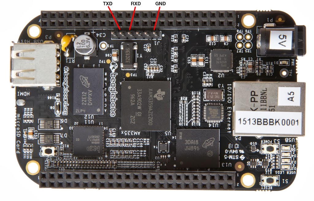
It plugs in to the pins right next to the "P9" header, on the
power-supply-plug side of the board.
The header has six pins: plug the black wire (ground) into pin 1,
the one closest to the power plug and ethernet jack. Plug the green wire
(RXD) into pin 4, and the white wire (TXD) into 5, the next-to-last pin.
Do not plug in the red power wire -- leave it hanging.
It's 5 volts and might damage the BBB if you plug it in to the
wrong place.
In case my photo isn't clear enough (click for a larger image),
Here's a diagram made by a helpful person on #beagle:
BeagleBone
Black serial connections.
Once the cable is connected, now what? Easy:
screen /dev/ttyUSB0 115200
That requires read-write privileges on the serial device /dev/ttyUSB0;
if you get a Permission Denied type error, it probably means you need
to add yourself to group dialout. (Changing groups requires logging out
and logging back in, so if you're impatient, just run screen as root.)
I used the serial monitor while flashing my new Angstrom image
(which is how I found out about how it spends most of that hour
updating Gnome desktop stuff). On the Raspberry Pi, I was dependent
on the serial cable for all sorts of things while I worked on hardware
projects; on the BeagleBone, I suspect I may use the USB networking
feature a lot more. Still, the serial cable will be handy to have when
things go wrong, or if I use a different Linux distro (like Debian) that
doesn't enable the USB networking feature.
Tags: hardware, linux, beaglebone, maker
[
19:41 Jul 16, 2013
More hardware |
permalink to this entry |
]
Sat, 13 Jul 2013
I finally got a shiny new BeagleBone Black! This little board
looks like it should be just the ticket for robotics, a small, cheap,
low-power Linux device that can also talk to hardware like an Arduino,
with plenty of GPIO pins, analog, PWM, serial, I2C and all.
I plugged in the BeagleBone Black via the mini USB cable, and it
powered up and booted. It comes with a Linux distro, Angstrom, already
installed on its built-in flash memory. I had already known that it
would show up as a USB storage device -- you can mount it like a disk,
and read the documentation (already there on the filesystem) that way.
Quite a nice feature.
What I didn't know until I read the
Getting
Started guide was that it had an even slicker feature: it also
shows up as a USB network device.
All I had to do was run a script,
mkudevrule.sh,
to set up some udev rules, and then
ifconfig -a on my desktop showed a new device named eth1.
The Beagle is already configured as 192.168.7.2, so I configured eth1
to be on the same network:
ifconfig eth1 192.168.7.1
and I was able to point my browser directly at a mini http server
running on the device, which gives links to all the built-in documentation.
Very slick and well thought out!
But of course, what I really wanted was to log in to the machine
itself. So I tried ssh 192.168.7.2 and ... nothing.
It turns out that the Angstrom that ships on current BBBs has a bug,
and ssh often doesn't work. The cure is to download a new Angstrom
image and re-flash the machine.
It was getting late in the evening, so I postponed that until the
following day. And a good thing I did: the flashing process turned out
to be very time consuming and poorly documented, at least for Linux users.
So here's how to do it.
Step 1: Use a separate power supply
Most of the Beaglebone guides recommend just powering
the BBB through its provided mini USB cable. Don't believe it.
At least, my first attempt at flashing failed, while repeating
exactly the same steps with the addition of an external power supply
worked just fine, and I've heard from other people who have had
similar problems trying to power the BBB through cable USB cable.
Fortunately, when I ordered the BBB I ordered a 2A power supply with
it. It's hard to believe that it ever really draws 2 amps, but that's
what Adafruit recommended, so that's what I ordered.
One caution: the BBB will start booting as soon as you
apply any power, whether from an external supply or the USB cable.
So it might be best to leave the USB cable disconnected during
the flashing process.
Get the eMMC-flasher image and copy it to the SD card
Download the image for the BeagleBone Black eMMC flasher from
Beagleboard
Latest Images.
They don't tell you the size of the image, but it's 369M.
The uncompress it. It's a .xz file, which I wasn't previously familiar
with, but I already had an uncompressor for it, unxz:
unxz BBB-eMMC-flasher-2013.06.20.img.xz
After uncompressing, it was 583M.
You'll need a microSD card to copy the image to. The Beagleboard folks
don't say how much space you need, but I found a few pages
talking about needing a 4G card. I'm not clear why you'd need that
for an image barely over half a gig, but 4G is what I happened to
have handy, so that's what I used.
Put the card in whatever adapter you need, plug it in to your Linux
box, and unmount it if got mounted automatically. Then copy the image
to the card -- just the base card device, not the first partition.
Replace X with the appropriate drive name (b in my case):
dd bs=1M if=BBB-eMMC-flasher-2013.06.20.img of=/dev/sdX
The copy will take quite a while.
Boot off the card
With the BBB powered off, insert the microSD card.
Find the "user boot" button. It's a tiny button right on top of the
microSD card reader. While holding it down, plug in your power supply
to power the BBB on. Keep holding the button down until you see all
four of the bright blue LEDs come on, then release the button.
Then wait. A long time. A really long time.
The LEDs should flash erratically during this period.
Most estimates I found on the web estimated 30-45 minutes to flash a
new version of Angstrom, but for me it took an hour and six minutes.
You'll know when it's done when the LEDs stop blinking erratically.
Either they'll all turn on steady (success) or they'll all go off
(failure).
Over an hour? Why so long?
I wondered that, of course, so in my second attempt at flashing, once
I had the serial cable plugged in, I ran ps periodically to see what
it was doing.
And for nearly half that time -- over 25 minutes -- what it was doing
was configuring Gnome.
Seriously. This Angstrom distribution for a tiny board half the size
of your hand runs a Gnome desktop -- and when it flashes its OS,
it doesn't just copy files, it runs Gnome configuration scripts for
every damn program on the system.
Okay. I'm a little less impressed with the Beagle's Angstrom setup now.
Though I still think this USB-ethernet thing is totally slick.
Tags: hardware, linux, beaglebone, maker
[
14:30 Jul 13, 2013
More hardware |
permalink to this entry |
]