Shallow Thoughts : tags : robots
Akkana's Musings on Open Source Computing and Technology, Science, and Nature.
Sat, 29 Jun 2013
![[GetSET Robots and Sensors workshop]](http://shallowsky.com/blog/images/getset2013/img_7756.jpg) Wednesday I taught my "Robotics and Sensors" workshop at
the SWE GetSET summer camp.
Wednesday I taught my "Robotics and Sensors" workshop at
the SWE GetSET summer camp.
It was lots of fun, and definitely better than last year. It helped that
I had a wonderful set of volunteers helping out -- five women from
CodeChix (besides myself), so we had
lots of programming expertise, plus a hardware engineer who was
wonderfully helpful with debugging circuits. Thanks so much to all the
volunteers! You really made the workshop!
We also had a great group of girls -- 14 high school seniors, all smart
and motivated, working in teams of two.
How much detail?
One big issue when designing a one-day programming workshop is how
much detail to provide in each example, and how much to leave to the
students to work out. Different people learn differently. I'm the sort
who learns from struggling through a problem, not from simply copying
an example, and last year I think I erred too much in that direction,
giving minimal information and encouraging the girls to work out the rest.
Some of them did fine, but others found it frustrating. In a one-day
workshop, if you have to spend too much time working everything out,
you might never get to the fun stuff.
So this year I took a different approach. For each new piece of hardware,
I gave them one small, but complete, working example, then suggested
ways they could develop that. So for the first example
(File->Examples->Basic->Blink is everyone's first
Arduino exercise), I gave everyone two LEDs and two resistors, and
as soon as they got their first LED blinking, I encouraged them to
try adding another.
It developed that about half the teams wired their second
LED right next to the first one, still on pin 13. Clever! but not what
I'd had in mind.
So I encouraged them to try moving the second LED to a different pin,
like pin 12, and see if they could make one LED turn on while the
other one turned off.
Another challenge with workshops is that people work at very different
speeds. You have to have projects the fast students can work on to keep them
from getting bored while the rest are catching up. So for LEDs, having
a box full of extra LEDs helped, and by the time we were ready to move on,
they had some great light shows going -- tri-colored blinkers, fast
flashers, slow double-blinks.
I had pushbuttons on the tentative agenda but I was pretty sure that
we'd skip that part. Pushbuttons are useful but they aren't really all
that much fun. You have to worry about details like pull-down resistors
and debouncing, too much detail when you have only six hours total.
Potentiometers are more rewarding. We went through
File->Examples->03.Analog->AnalogInput,
and a few teams also tried LED fading with
File->Examples->03.Analog->AnalogInOutSerial.
Music
![[GetSET Robots and Sensors workshop]](http://shallowsky.com/blog/images/getset2013/img_7761.jpg) But then we moved on to what was really the highlight of the day,
piezo speakers.
Again, I provided a small working
example
program to create a rising tone. The Arduino IDE has no good
speaker examples built in, so I'd made a short url for my
Robots and Sensors
workshop page,
But then we moved on to what was really the highlight of the day,
piezo speakers.
Again, I provided a small working
example
program to create a rising tone. The Arduino IDE has no good
speaker examples built in, so I'd made a short url for my
Robots and Sensors
workshop page, is.gd/getset, to make it easyto
copy/paste code. It took no time at all before their speakers were
making noise.
I was afraid they'd just stop there ...
but as it turned out, everybody was energized
(including me and the other volunteers) by all the funny noises,
and without any prompting the girls immediately got to work changing
their tones, making them rise faster or slower, or (with some help
from volunteers) making them fall instead of rise. Every team had
different sounds, and everybody was laughing and having fun as they
tweaked their code.
In fact, that happened so fast that we ended up with plenty of time
left before lunch. My plan was to do speakers right before lunch because
noise is distracting, and after you've done that you can't to
concentrate on anything else for a while. So I let them continue to
play with the speakers.
I was glad I did. At least three different teams took the initiative
to search the web and find sample code for playing music.
There were some hitches -- a lot of the code samples needed to be
tweaked a bit, from changing the pin where the speaker was plugged in,
to downloading an include file of musical notes. One page gave code
that didn't compile at all. But it was exciting to watch -- after all,
this sort of experimentation and trial-and-error is a big part
of what programmers do, and they all eventually got their music projects
working.
One thing I learned was that providing a complete working
.ino file makes a big difference. Some of the "music on Arduino"
pages the girls found provided C functions but no hints as to how
to call those functions. (It wasn't obvious to me, either.)
Some of my own examples for the afternoon projects were like that,
providing code snippets without setup() and loop(), and some teams
were at sea, unsure how to create setup() and loop(). Of course
I'd explained about setup() and loop() during the initial blink
exercise. But considering how much material we covered in such a short
time, it's not reasonable to expect everybody to remember details like
that. And the Arduino IDE error messages aren't terribly easy to read,
especially showing up orange on black in a tiny 3-line space at the
bottom of the window.
So, for future workshops, I'll provide complete .ino files for all my
own examples, plus a skeleton file with an empty setup() and loop()
already there.
It's okay to spoon feed basic details like the structure of an .ino
file if it gives the students more time to think about the really
interesting parts of their project.
Afternoon projects
![[Working on the robotic car]](http://shallowsky.com/blog/images/getset2013/img_7766.jpg) After lunch, the afternoon was devoted to projects. Teams could pick
anything we had hardware for, work on it throughout the afternoon and
present it at the end of the workshop. There were two teams working on
robotic cars (sadly, as with so many motor projects, the hardware
ended up being too flaky and the cars didn't do much).
Other teams worked with sonar rangefinders, light sensors or tilt
switches, while some continued to work on their lights and music.
After lunch, the afternoon was devoted to projects. Teams could pick
anything we had hardware for, work on it throughout the afternoon and
present it at the end of the workshop. There were two teams working on
robotic cars (sadly, as with so many motor projects, the hardware
ended up being too flaky and the cars didn't do much).
Other teams worked with sonar rangefinders, light sensors or tilt
switches, while some continued to work on their lights and music.
Everybody seemed like they were having a good time, and I'd seen a lot of
working (or at least partly working) projects as I walked around
during the afternoon, but when it came to present what they'd done,
I was a little sad.
There was a lot of "Well, I tried this, but I couldn't get it to work,
so then I switched to doing this." Of course, trying things and
changing course are also part of engineering ... that sentence
describes a lot of my own playing with hardware, now that I think of
it. But still ... I was sad hearing it.
Notes for next time
So, overall, I was happy with the workshop. I haven't seen the evaluation
forms yet, but it sure seemed like everybody was having fun,
and I know we volunteers did.
What are the points I want to remember for next time?
- Start with small but complete working examples to introduce each
new hardware component.
- Provide complete .ino files, not just code snippets.
- Skip pushbuttons, but do try to cover AnalogInOutSerial and PWM output.
Or at least have printed handouts explaining the PWM outputs and LED fading.
- Turnkey kits are good: the less "connect the blue wire to pin 7,
the green one to pin 8" the better. For things like cars, I'd
like something already wired up with battery and shield,
"Just add Arduino".
- Keep a closer eye on the afternoon projects -- try to make sure
each team has something they're proud to show off.
Thanks again to the great volunteers! I'm looking forward to giving
this workshop again.
Tags: robots, arduino, education, hardware, programming, maker
[
20:36 Jun 29, 2013
More education |
permalink to this entry |
]
Thu, 30 May 2013
Last summer I led a
one day robotics workshop
for high school girls
as part of the Society of Women Engineers'
GetSET summer camp.
I'm giving it again this year, on June 26.
We're still lining up volunteers to help teach the workshop,
and I'd love help from bay area women -- you don't have to be a
robotics or programming expert, just willing to learn and play.
The workshop is based around the
Arduino open-source
microcontroller: we hook up Arduinos, then wire up LEDs, buzzers
and other parts on breadboards and make them do things.
It's a programming workshop as well as a hardware one:
most of the girls had a workshop the previous summer on
Ruby programming,
but that's their only exposure to programming.
So it's a challenge to see how much we can cover in one day --
and a testament to the girls that they do so well.
Last year we spent the morning covering wiring Arduinos to the basics
like breadboards, LEDs, pushbuttons and potentiometers. Then in the
afternoon, teams worked on projects --
some of them wired together lots of colored LEDs, some worked with
making sounds with buzzers, and one team built a robotic truck.
I was hoping to be able to show them more motorized projects,
and I'd brought several toy cars and trucks scavenged from thrift
shops (radio controlled toys that had lost their radio controller).
But
the
wiring needed for the H-bridge to control the motor is complex,
and the team that chose the truck project had their hands full getting
the truck running by the end of the day -- forget about adding
any bells and whistles. I wanted to make that easier.
![[Homemade, super cheap Arduino motor shield]](http://shallowsky.com/blog/images/hardware/motorshield/motorshield1T.jpg)
So for this year, with a little more time to prepare,
I'm wiring up some Arduino motor shields.
Shields are devices that stack on top of an Arduino. You can do all
the difficult wiring beforehand, and just plug in the shield when you're
ready to use it. The down side is that shields can be expensive --
motor shields typically cost around $25. That's okay if you're buying
one, but if you're trying to outfit a classroom, that can add up
pretty quickly.
But I found a way of building motor shields cheaply. The H-bridge chip
I'm using, the
SN754410, is $1.75 at Jameco
if you buy 5 or more.
Jameco also carries a proto-shield
PC board
($4.25 in quantity) and
stacking
headers ($1.59). So that's only $7.59 per shield, plus shipping,
not counting a few sundries like battery connectors that I'd already
bought for last year's class.
Then I had to wire up the shields. I was all fired up about having a
good excuse to use wire-wrap instead of soldering. But then I realized
that tiny 30-gauge wire-wrap wire probably wasn't adequate for the current
going to the motors. So I soldered wires for the motors,
the power lines from the battery connector to the H-bridge chip,
and from the battery connector to the Arduino's Vin.
Then I wire-wrapped everything else.
![[Car sporting super cheap Arduino motor shield]](http://shallowsky.com/blog/images/hardware/motorshield/car-motorshieldT.jpg)
The end result looks nice and clean from the top (please avert your
eyes from my messy soldering underneath). There's no scary rats-nest
of wires, like with the breadboards I used last year, and there's plenty
of empty space on the board to velcro a battery or attach sensors like
an ultrasonic rangefinder. I think this will work well and will
encourage the girls to get some little cars zipping around the
computer room.
I'm looking forward to setting up some simple projects I can
combine with the cars -- light sensors, sonar or IR rangefinders,
other ideas? I'd love suggestions from anybody, and I'd especially
love to line up some volunteers (women only for the day of the
workshop, please).
Workshop day -- June 26 -- mostly means walking around checking on how
the girls are doing, cheering them on, helping them debug problems by
checking their wiring and looking over their programs (very simple
code -- remember, they've never seen C code before).
And if anybody (male or female) wants to get together before the
workshop and play with Arduinos, help me solder the rest of the shields,
and brainstorm fun projects for the girls, please drop me a line!
The rough outline, handouts and wiring diagrams so far are at my
Robots and Sensors Workshop
page.
Tags: arduino, hardware, robots, maker
[
19:40 May 30, 2013
More hardware |
permalink to this entry |
]
Sat, 18 May 2013
In my post about
Controlling
a toy car with a Raspberry Pi, I skipped over one important detail:
the battery. How do you power the RPi while it's driving around the room?
Most RPi sites warn that you shouldn't use the Pi with a power supply
drawing less than an amp. I suspect that's overstated, and it probably
doesn't draw more than half of that most of the time; but add the draw
of two motors and we're talking a fairly beefy battery, not a couple
of AAs or a 9V.
Luckily, as an R/C plane pilot,
I have a fridge full of small 2- and 3-cell lithium-polymer batteries
(and a li-po charger to go with them). The problem is:
the Pi is rather picky about its input voltage. It wants 5V and nothing
else. A 2-cell li-po is 7.4V. So I needed some sort of voltage regulator.
![[5V voltage regulator]](http://www.jameco.com/Jameco/Products/ProdImag/51262.jpg) It's easy enough to get a simple
5V
voltage regulator (pictured at right) -- 30c at Jameco, not much
more locally. But they're apparently fairly inefficient, and need a
heat sink for high current loads.
It's easy enough to get a simple
5V
voltage regulator (pictured at right) -- 30c at Jameco, not much
more locally. But they're apparently fairly inefficient, and need a
heat sink for high current loads.
![[5V step-down power converter]](http://www.adafruit.com/images/ID1065.jpg) So I decided to blow the big bucks ($15) for a
5V step-down power
converter (left) that claims to be 94% efficient with no need for
a heat sink.
So I decided to blow the big bucks ($15) for a
5V step-down power
converter (left) that claims to be 94% efficient with no need for
a heat sink.
Unlike most of Adafruit's products, this one comes with no tutorials
and no hints as to pinouts, but after a little searching, I determined
that the pins worked the same way as the cheap voltage regulators.
With the red logo facing you, the left pin (your left) is input power
from the battery; middle is ground (connect this to the battery's
ground which is shared with the Pi's ground); the right pin is the
regulated 5V output, which goes to pin 2 on the Pi's GPIO connector.
I was able to run both the RPi and the motor drive circuit off the
same 7.4 volt 2-cell li-po battery (which almost certainly wouldn't
work with 4 AAs, though it might work with 8). A 500 mAh battery seems
to be plenty to drive the RPi and the car, though I don't know how long
the battery life will be. I'll probably be using 610 mAh batteries for
most of my testing, since I have a collection of them for the aerial
combat planes.
Here's a wiring diagram made with Fritzing
showing how to hook up the battery to power a RPi. If you're driving motors,
you can run a line from the battery's + terminal (the left pin of the
voltage regulator) as your motor voltage source, and use the right pin
as your 5V logic source for whatever motor controller chip you're using.
![[Battery-powered Raspberry Pi]](http://shallowsky.com/blog/images/hardware/pi-battery-bb.jpg)
Tags: hardware, raspberry pi, robots, maker
[
17:50 May 18, 2013
More hardware |
permalink to this entry |
]
Sun, 12 May 2013
![[Raspberry Pi robotic car]](http://shallowsky.com/blog/images/rpi/img_7522T.jpg)
In my previous article about
pulse-width
modulation on Raspberry Pi, I mentioned that the reason I wanted
PWM on several pins at once was to drive several motors, for a robotic car.
But there's more to driving motors than just PWM. The GPIO output pins
of a Pi don't have either enough current or enough voltage to drive
a motor. So you need to use a separate power supply to drive the motors,
and do some sort of switching -- at minimum, a transistor or relay for
each motor.
There are lots of motor driver chips. For Arduinos, "motor shields",
and such things are starting to become available for the Pi as well.
But motor shields are expensive, usually more than the Pi costs
itself. If you're trying to outfit a robotics class, or to help
low-income students build robots, it's not a great solution.
When I struggled with this problem for the Arduino, the solution I
eventually hit on was a
SN754410
H-bridge chip. For under $2, you get bidirectional control of two
DC motors. For each motor, you send input to the chip via a PWM line
and two directional control lines.
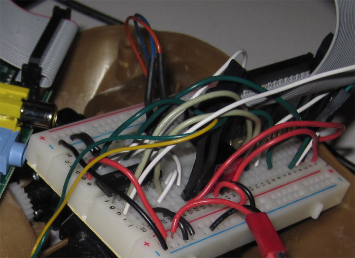
![[Snarl of wires driving a car with a Raspberry Pi]](http://shallowsky.com/blog/images/rpi/img_7514T.jpg) The only problem is the snarl of wiring. One PWM and two direction
lines per motor is six wires, plus power for the chip's logic side,
power for the motors, and ground, and the three pins for a serial cable,
and you're talking a lot of wires to plug in.
Although this is all easy in comcept, it's also easy
to get a wire plugged in one spot over on the breadboard from where
it ought to be, and then nothing works.
The only problem is the snarl of wiring. One PWM and two direction
lines per motor is six wires, plus power for the chip's logic side,
power for the motors, and ground, and the three pins for a serial cable,
and you're talking a lot of wires to plug in.
Although this is all easy in comcept, it's also easy
to get a wire plugged in one spot over on the breadboard from where
it ought to be, and then nothing works.
I spent too much time making tables of what should get plugged into where.
I ended up with a table like this:
| Pi connector pin | GPIO (BCM) | SN754410 pin
|
| Pi 2 | 5V power | Breadboard bottom V+ row
|
| Pi 18 | 24 | 1 (motor 1 PWM)
|
| Pi 15 | 22 | 1 (motor 0 PWM)
|
| Pi 24 | 8 (SPI CE0) | 4 (motor 1 direc 0)
|
| Pi 26 | 7 (SPI CE1) | 14 (motor 1 direc 1)
|
| Pi 25 | Gnd | Breadboard both grounds
|
| Pi 19 | 10 (MOS1) | 3 (motor 0 direc 0)
|
| Pi 21 | 9 (MOS0) | 13 (motor 0 direc 1)
|
| motor 0 | | 5, 11
|
| motor 1 | | 6, 12
|
... though, as you'll see, some of those pin assignments ended up
getting changed later.
One more thing: I found that I had to connect the chip's logic V+
(pin 2 on the SN754410) to the 5v pin on the RPi, not the 3.3V pin.
The SN754410 is okay with 3.3V logic signals, but it seems to need
a full 5V of power.
Programming it
The software control is a little trickier than it ought to be, too,
because of the 2-wire control lines on each motor. With both lines high
or both lines low, nothing moves. (Some motor driver chips distinguish
between those two states: e.g. both low might be a brake, while both
high lets the motor freewheel; but I haven't seen anything indicating
the SN754410 makes any distinction.) Then set one line high, the other
low, and the motor spins one way; reverse the lines, and the motor
spins the other way. Assuming, of course, the PWM line is sending
a signal.
Of course, you need RPI.GPIO version 0.5.2a or later to do any of this
PWM control. Get it via pip install --upgrade RPi.GPIO
-- the RPI.GPIO in Raspbian mis-reports its version and is really 0.5.1a.
Simple enough in concept. Okay, now try explaining that to beginning
programmers. No, thanks! So I wrote a PiMotor class in
Python that takes care of all those details. Initialize it with the pins
you want to use, then use calls like set_speed(s)
and stop(). It's on GitHub at
pimotors.py.
I put the H-bridge chip on a breadboard, wired up all the lines to the
Pi and a lithium-polymer airplane battery, and (after several hours of
head-banging while I found all the errors in my wiring), sure enough,
I could get the motors to spin.
But one thing I found while wiring was that I couldn't always use the
GPIO lines I'd intended to use. The RPi has seemingly a lot of GPIO
lines -- but
nearly all of
the GPIO lines have other purposes, except I haven't found any
good explanation of what those uses are and how to know when they're
in use. I found that quite frequently, I'd try a
GPIO.setup(pin, GPIO.OUT) and get
"This channel is already in use". Sometimes GPIO.cleanup()
helped, and sometimes it didn't. None of this stuff has much
documentation, and I haven't found any IRC channel or mailing list
for discussing RPi GPIO. And of course, there's no relation between
the pin number on the header and the GPIO pin number. So I spent a lot
of time counting breadboard rows and correlating to a printout I'd made
of the RPi's GPIO socket.
Putting the circuit on a proto-board
Once I got it working, I realized how much I didn't relish the
thought of ever doing it again -- like whenever I needed to unplug
the motors from the Pi and use it for something else.
Fortunately, at some point I'd bought an
Adafruit Pi Plate,
sort of the RPi equivalent of Adafruit's Arduino ProtoShield. I love
protoshields. I have a bunch of them, and I use them for all sorts of
Arduino projects, so I'd bought the Pi Plate thinking it might come in
handy some day. It's not quite like a protoshield, because it's
expensive and heavy, loaded up with lots of pointless screw terminals.
But you don't have to solder the screw terminals on; just solder the
headers and you have a protoshield for your RPi on which you can put
a mini breadboard and build your motor circuit.
I do wish, though, that Adafruit or someone made a simple, basic
proto board PCB with headers for the Pi. No screw terminals, no extra
parts, just the PCB and headers, to make it easy and cheap to swap
between different RPi projects. The
HobbyTronics
Slice of Pi looks intriguing, but the GPIO pins it exposes don't seem
to be the same ones exposed on the RPI's GPIO header. I'd be
interested in hearing from anyone who's tried one of these.
![[Raspberry Pi motor circuitn]](http://shallowsky.com/blog/images/rpi/motors-pi-plateT.jpg) Anyway, with the Pi Plate shield, my motor circuit looks much neater,
and I can unplug it from my RPi without fear that it'll mean
another half hour if I ever want to get the motors hooked up again.
I did have to change some of the pin assignments yet again, because
the Pi Plate doesn't expose all the GPIO pins available on the RPi header.
I ended up using 25, 23, 24 for the first motor, and 17, 21, 22 for
the second.
Anyway, with the Pi Plate shield, my motor circuit looks much neater,
and I can unplug it from my RPi without fear that it'll mean
another half hour if I ever want to get the motors hooked up again.
I did have to change some of the pin assignments yet again, because
the Pi Plate doesn't expose all the GPIO pins available on the RPi header.
I ended up using 25, 23, 24 for the first motor, and 17, 21, 22 for
the second.
I wanted to make a circuit diagram with Fritzing, but it turns out the
Fritzing I have can't import part definitions like the one for
Raspberry Pi, and the current Fritzing doesn't work on Debian Wheezy.
So that'll have to wait. But here's a photo of my
breadboarded circuit on the Pi Plate, and a link to my
motor
breadboarded circuit using a cable to the GPIO.
Kevin Mark tipped me off that Fritzing is quite easy to build under
Debian, if you first
apt-get install qt4-qmake libqt4-dev libboost1.49-dev
I had to add one more package to Kevin's list, libqt4-sql-sqlite,
or I got a lot of QSQLITE driver not loaded and other errors
on the terminal, and a dialog saying "Unable to find the following 114 parts"
followed by another dialog too big to fit on the screen with a list of
all the missing parts.
Once those packages are installed, download the Fritzing source tarball,
qmake, make, and sudo make install.
And my little car can go forward, spin around in both directions, and
then reverse! Now the trick will be to find some sensors I can use with
the pins remaining ...
Tags: hardware, raspberry pi, robots, maker
[
14:08 May 12, 2013
More hardware |
permalink to this entry |
]
Sat, 04 May 2013
I've written about how to
drive
small DC motors with an Arduino, in order to
drive
a little toy truck around.
But an Arduino, while great at talking to hardware, isn't very powerful.
It's easy to add simple sensors to the truck so it can stop before hitting
the wall; but if I wanted to do anything complicated -- like, say,
image processing with a camera -- the Arduino really isn't enough.
![[Raspberry Pi set up for motor control]](http://shallowsky.com/blog/images/hardware/img_7494.jpg) Enter Raspberry Pi. It isn't a super-fast processor either, but it's
fast enough to run Linux, Python, and image processing packages like
SimpleCV.
A Raspberry-Pi driven truck would be a lot more powerful: in theory,
I could make a little Mars Rover to drive around my backyard.
If, that is, I could get the RPi driving the car's motors.
Enter Raspberry Pi. It isn't a super-fast processor either, but it's
fast enough to run Linux, Python, and image processing packages like
SimpleCV.
A Raspberry-Pi driven truck would be a lot more powerful: in theory,
I could make a little Mars Rover to drive around my backyard.
If, that is, I could get the RPi driving the car's motors.
Raspberry Pi, sadly, has a lot of limitations as a robotics platform.
It's picky about input voltages and power; it has no analog inputs,
and only one serial port (which you probably want to use for a console
if you're going to debug your robot reliably).
But my biggest concern was that it has only one pulse-width modulation
(PWM) output, while I needed two of them to control the car's two motors.
It's theoretically possible to do software PWM on any pin -- but
until recently, there were no libraries supporting that.
Until recently. I've been busy for the last month or two and haven't
been doing much RPi experimenting. As I got back into it this week, I
discovered something delightful: in the widely available python library
RPi.GPIO,
Software PWM is available starting with 0.5.2a.
Getting the right RPi.GPIO
Just what I'd been wanting! So I got an LED and resistor and plugged
them into a breadboard.
I ran a black wire from the RPi's pin 6, ground, to the short LED pin,
and connected the long pin via the resistor to the RPi's pin 18
(GPIO 24) (see the
RPi Low-level
peripherals for the official GPIO pin diagrams).
With the LED wired up, I
plugged
in my serial cable, powered up the RPi with its Raspbian SD card,
and connected to it with screen /dev/ttyUSB0 115200.
I configured the network to work on my local net and typed
sudo apt-get install python-rpi.gpio
to get the latest version. It got 0.5.2a-1. Hooray!
I hurried to do a test:
pi@raspberrypi:~$ sudo python
Python 2.7.3 (default, Jan 13 2013, 11:20:46)
[GCC 4.6.3] on linux2
Type "help", "copyright", "credits" or "license" for more information.
>>>
>>> import RPi.GPIO as GPIO
>>> GPIO.setmode(GPIO.BCM)
>>> GPIO.setup(24, GPIO.OUT)
>>> led = GPIO.PWM(24, 100)
Traceback (most recent call last):
  File "<stdin>", line 1, in <module>
AttributeError: 'module' object has no attribute 'PWM'
Whoops! But Raspbian said it was the right version ...
I checked again with aptitude show python-rpi.gpio --
yep, 0.5.2a-1. Hmph!
After some poking around, I discovered that help(GPIO),
after printing out an interminable list of exception classes,
eventually gets to this:
VERSION = '0.5.1a'
In other words, Rapsbian is fibbing: that package that Raspbian says
is version 0.5.2a-1 is actually version 0.5.1a.
(This is the sort of thing that makes Raspberry Pi such a joy to work with.
Yes, that's sarcasm.)
Okay. Let's try removing that bogus Raspbian package and getting it from
pypi instead:
apt-get remove python-rpi.gpio
pip install --upgrade RPi.GPIO
Then I tried the same test as before. Success!
And now I was able to set the LED to half brightness:
led.start(50)
I was able to brighten and dim the LED at will:
led.ChangeDutyCycle(90)
led.ChangeDutyCycle(25)
I played with it a little while longer, then cleaned up:
led.stop()
GPIO.cleanup()
If you're experimenting with RPi.GPIO's PWM, you'll want to check
out this useful 2-part tutorial:
What about motors?
So PWM works great for LEDs. But would it drive my little robotic car?
I unplugged my LED and wired up one of the
SN754410
motor drivers circuits I'd wired up for the Arduino. And it worked
just as well! I was able to control the motor speed using ChangeDutyCycle().
I'll write that up separately, but I do have one caveat:
GPIO.cleanup(), for some reason, sets the pin output to HIGH.
So if you have your car plugged in and sitting on the ground when you
run cleanup(), it will take off at full speed.
I recommend testing with the car on a stand and the wheels off the ground.
Update: the motor post is up now, at
Driving
two DC motors with a Raspberry Pi.
Tags: raspberry pi, hardware, electronics, robots, maker
[
21:00 May 04, 2013
More hardware |
permalink to this entry |
]
Tue, 06 Mar 2012
![[Linux controlled Air Swimmers flying robotic shark]](http://shallowsky.com/blog/images/arduino/Air-Swimmers-TM-Radio-Controlled-Flying-Shark.jpg) I got a request from SVLUG to fill in at the last minute for a speaker
with a health emergency. Fortunately, I'd been slated to give them my
Arduino talk from SCALE in a few months, so I was happy to accept.
I'm always glad for a chance to show off Bruce, my
Arduino-
and Linux-controlled 6-foot flying robotic shark.
I got a request from SVLUG to fill in at the last minute for a speaker
with a health emergency. Fortunately, I'd been slated to give them my
Arduino talk from SCALE in a few months, so I was happy to accept.
I'm always glad for a chance to show off Bruce, my
Arduino-
and Linux-controlled 6-foot flying robotic shark.
And if anyone
reading this happens to be in town for PyCon, Symantec isn't that
far from Santa Clara, roughly a 10-minute drive ... and I promise there
will be at least two interesting Python scripts presented.
It's free, of course, so come hear the talk!
Here are the SVLUG meeting
details and directions.
Tags: speaking, arduino, hardware, robots, radio control, maker
[
19:25 Mar 06, 2012
More speaking |
permalink to this entry |
]
Sat, 11 Feb 2012
![[Arduino-powered truck]](http://shallowsky.com/arduino/slides/pix/projects/messytruck.jpg)
This is the story of my adventures learning to drive a little toy truck
from an Arduino: specifically, how to drive the motors.
Motor control turned out to be trickier than I expected, and I don't
see a lot of "Arduino motor control for dummies" pages on the web,
so I'm writing one.
My truck is from a thrift shop. It has two brushed motors (about 280-350
size, in R/C plane parlance). It was originally radio controlled.
It has space for 4 AA batteries, nominal 6v, which I thought should be perfect
for the Arduino.
Connecting directly to the Arduino (don't)
First, you can drive a small motor directly by plugging one lead into
ground and the other into an Arduino digital or analog output line.
(Analog output isn't real analog output -- it uses PWM, pulse width modulation.)
Don't do this. You risk damaging your Arduino, either by putting
too much current through it (the Arduino maxes out at 40ma per pin, 200ma
total; a small motor can pull several amps), or from
back-EMF when
the motor stops.
Motor shields
![[Freeduino motor shield]](http://shallowsky.com/arduino/slides/pix/arduinos/motorshield.jpg) Lots of Arduino-oriented shops sell "motor shields". I bought a
Freeduino
motor shield because I could get it from Amazon and it was cheap.
It's a kit you have to solder together, but it's a very easy soldering job.
The demo code is easy, too. I wired it up to the Arduino, loaded the demo
code, hooked up my Arduino to the truck's onboard batteries, and ...
nothing. Sometimes the motor would twitch a bit, or hum, but the truck
didn't move.
Lots of Arduino-oriented shops sell "motor shields". I bought a
Freeduino
motor shield because I could get it from Amazon and it was cheap.
It's a kit you have to solder together, but it's a very easy soldering job.
The demo code is easy, too. I wired it up to the Arduino, loaded the demo
code, hooked up my Arduino to the truck's onboard batteries, and ...
nothing. Sometimes the motor would twitch a bit, or hum, but the truck
didn't move.
I wondered if maybe it was something about the batteries (though they
were brand new). I tried plugging the Arduino in to the universal AC
power supply I use for testing. No improvement.
At first I suspected that the motor shield was junk because its 1 amp
maximum wasn't enough. But I was wrong -- the problem was the batteries.
Neither the truck's 4xAA batteries nor the (supposedly) 1 amp AC adaptor could
put out enough current to drive motors.
When it finally occurred to me to try
a lithium-polymer model airplane battery (2 cells, 7.4 volts, 500 mAh),
the truck immediately zipped across the floor and smashed into a chair leg.
So motor shields work fine, and they're very easy to use -- but don't
underestimate the importance of your power supply. You need a battery
capable of supplying a fairly beefy current.
But why is that, when the truck was designed for 4xAA batteries?
Well, the 4xAAs can drive the motors, but they can't drive the motors,
the Arduino and the shield all at the same time. If I power the
Arduino separately off a 9v battery, the truck will move. It doesn't zip
across the room like with the li-po battery, but at least it moves.
Motor Driver
So I had a solution. Except I wanted something a little cheaper. A
$20-30 motor shield is fine for a one-time project, but I was also
shopping for parts to teach a summer camp class in robotics. We're on
a shoestring budget, and an additional $20 per team is a little too much.
![[Pololu TB6612FNG Dual Motor Driver]](http://b.pololu-files.com/picture/0J903.200.jpg?2f6bdb33ecdebb9d8f4d69952fa75527) On a recommendation from Eugene at
Linux Astronomy, who's been
teaching wonderful robotics classes for several years, I discovered
Pololu as a source of robotics
equipment. Poking around their site, I found the
TB6612FNG Dual
Motor Driver Carrier, which is under $8 in quantity. Sounded like
a much better deal, so I ordered one to try it out.
On a recommendation from Eugene at
Linux Astronomy, who's been
teaching wonderful robotics classes for several years, I discovered
Pololu as a source of robotics
equipment. Poking around their site, I found the
TB6612FNG Dual
Motor Driver Carrier, which is under $8 in quantity. Sounded like
a much better deal, so I ordered one to try it out.
The TB6612FNG comes with headers not yet soldered. I substituted female
headers, so it would be easier to plug in jumper wires to the Arduino
and the male leads from the motors.
Writing an Arduino program for the TB6612FNG is a little more
complicated than for the motor shield. It has two direction pins for
each motor, plus a STDBY pin you have to keep high. So there
are a lot more pins to manage, and when you change motor direction
you have to toggle two pins, not just one.
That'll make it more confusing for the students (who are
beginning programmers), but I've written wrappers like
drive(int whichmotor, int direc, int speed) to make it simpler.
The motor driver has the same power supply issue as the motor shield did:
I can't power it, the Arduino and the motors all from the 4xAA batteries.
Like the shield, it works okay with the Arduino on 9v, and great with
one li-po powering everything.
Electronic Speed Controllers
![[electronic speed controller]](http://shallowsky.com/arduino/slides/pix/projects/ESC.jpg)
I also tried using ESCs, the electronic speed controllers I've used
with radio controlled airplanes. You can talk to them using the Arduino
Servo library (there are lots of examples online). That works,
but there are two issues:
- ESCs all have wierd proprietary arming sequences,
so you have to figure out what they are (e.g. run the voltage up to maximum,
hold there for two seconds, then down to zero, then hold for two seconds,
then you're ready to drive) and write that into your code. If you switch
ESCs, you may have to rewrite the arming code.
- ESCs only go in one direction -- fine for driving a truck forward,
not so good if you need to drive a steering motor both ways.
I'm sure ESCs have the same battery issue as the other two options,
but I didn't even try running one off the AAs.
Anyone who has ESCs sitting around probably has beefy batteries too.
Custom H-bridges
All the cool robotics hipsters (cHipsters?) buy H-bridge chips
and build their own circuits around them, rather than using things like
motor shields or motor drivers.
This
H-bridge
circuit by Bob Blick is one popular example.
(Those double-transistor-in-a-circle things are Darlington transistors.)
But a web search like arduino h-bridge circuit turns
up other options.
For driving big motors, you definitely need your own H-bridge circuit
(or an ESC), since all the available motor shields and drivers are
limited to 2 amps or less. For small motors like my toy truck,
I'm not sure what the advantage is. Except being one of the cool cats.
Summary
- For any sort of motor, either use a beefy battery (lithium polymer
is idea, but you need a special charger and safety precautions for them),
or use separate batteries for the Arduino and the motors.
- Motor shields are the easiest and most turnkey option.
- A motor driver is cheaper and smaller, but slightly more hassle to use.
- Use an ESC for big motors that only need to go in one direction,
or if you're already a model airplane junkie and have some lying around.
- Use a custom H-bridge circuit if you're a cHipster or you have a
really big motor project.
Tags: arduino, hardware, robots, maker
[
13:45 Feb 11, 2012
More hardware |
permalink to this entry |
]
Fri, 27 Jan 2012
When SCALE approved my talk proposal,
Fun
with Linux and Devices, I had a challenge: I needed some good,
visual Arduino demos that would work in front of an audience.
In particular, I wanted something that moved. A little toy truck?
A moving penguin? A rotating sunflower? I fiddled with this and that,
not fully satisfied with anything. And then suddenly I realized what I needed.
Something cool. Something BIG.
Something I'd been wanting an excuse to buy anyway.
An Air Swimmers Shark.
I'd seen these things on video, but never in person. They're available
all over, even on Amazon, so I put in an order there and got a shark
in a few days.
These things are ridiculous and cool. It's huge, about 5 feet long,
and filled with helium. It takes maybe half an hour to assemble.
It has a small motor to beat the tail, an infrared transmitter,
and a weighted receiver that moves back and forth on a track to tilt
the fish up or down as it swims.
Once it's assembled, you can get it filled with helium at a party
store (which costs $3 to $6 depending on where you go).
Once the shark is filled, you add clay as ballast until the shark is
neutrally buoyant, neither rising nor sinking. It's quite sensitive:
you'll find yourself needing to add or remove pea-sized chunks of clay
as the temperature in the room changes, but being a little over- or
under-ballasted doesn't hurt it much.
With its tail beating, the shark really does look like it's swimming
through the air.
My shark is named Bruce, after the mechanical shark used for the movie
"Jaws". My Bruce, I'm happy to say, has been much more tractable than
his famously intemperate namesake.
Okay, now how do we turn this ridiculous-but-cool thing into an Arduino
project?
Hacking the transmitter
![[Air Swimmers IR transmitter, front]](http://shallowsky.com/blog/images/arduino/img_5238.jpg)
There were two possible approaches. First, mount an Arduino directly
on the shark, and let it be totally self-directed. Second, patch the
Arduino into the shark's transmitter and control it from Linux.
I chose the second option, for several reasons. First, I was fairly
sure it would be easier, and less invasive (the shark would still be
usable with manual control). I also liked the idea of keeping the
transmitter as a manual override, in case my control program didn't
work right. Finally, I liked the idea of keeping a Linux machine in the
loop -- the shark would actually be controlled by Linux, not just by
the Arduino.
So the first thing I did was take the transmitter apart (4 Philips screws).
Inside are 4 pushbuttons, for right, left, up, and down, and the circuit
board is nice and simple. Whew -- this might be doable!
![[Air Swimmers IR transmitter, back]](http://shallowsky.com/blog/images/arduino/img_5245.jpg)
Four more screws and I had access to the back of the board, which was
equally simple. Now I could get my voltmeter on the contacts while I
pushed buttons.
It turned out the contacts (indicated with arrows on the photo) on the
downstream side of each switch were normally high (4.5 volts -- the transmitter
uses 3 AAA batteries). When I pushed the button, the contact went to ground.
Okay, so what I needed was some way for the Arduino to ground those
contacts at will.
First I needed to solder some wires to the contacts.
(How do you tell which side of the pushbutton is the one you need to solder?
Well, one side changes voltage when you press the button, and the other
side stays constant. The one that changes is the one you need to connect
to the Arduino, so the Arduino can change it too.)
I figured I needed 6 wires: ground, power, and one for each switch.
(It turned out I didn't need the power wire, but I figured it didn't
hurt to include it just in case.)
I wanted to have a nice small connector on the side of the transmitter,
but I couldn't find any 6-pin connectors that didn't look big and bulky,
so I gave up and decided I'd just let my ribbon cable dangle from the
transmitter. If I got a nice multi-colored one, maybe it would look festive.
I couldn't find any 6-conductor ribbon cable, so I got a
wider one and separated 6 wires from the rest. Then I soldered the
six wires to the appropriate places (marked by arrows in the photo).
On the other end, I tinned the six wires with solder so I could plug
the stranded wires into my breadboard.
Simulating button presses
I've done enough reading to know of three ways to simulate a button press.
You can put a relay between the two contacts of the switch; you can do
the same thing, but with an optocoupler (opto-isolator) instead of a relay;
or you can do some magic with a transistor. I was fuzzy on the
transistor magic bit, so a relay sounded easiest.
I played around with a relay and a spare switch and convinced myself I
knew how to wire them up. Then it was off to my local parts store to
buy four matched relays small enough to fit on my little mini breadboard.
There followed a several-day fiasco wherein I bought lots of relays
that turned out not to be suitable, and got increasingly frustrated at
how large and clunky all the available relays were.
There are smaller ones, but I couldn't get them to work.
And I learned that relays mostly come without documentation on which
pin does which, so there's a lot of experimenting with each new type.
Frustrated, I tried some optocouplers I'd bought on a whim last year.
No dice ... couldn't get them to work either.
![[testing my transistor circuit]](http://shallowsky.com/blog/images/arduino/img_5246.jpg)
Desperate, I turned to IRC, #arduino on Freenode. The folks there are
mostly electronics wizards, and I'm sure my questions must have seemed
very dumb, but they were patient with me, and pointed me toward
a very simple circuit,
LED4dummies,
that was just what I needed. (They also suggested
Wikipedia's Open
collector article, but I found that less clear.)
It took me some
experimenting with a transistor, an LED and a couple of resistors
(I blew out a couple of transistors before I realized I had the R2 resistor
in the wrong place) but eventually I got it working, and felt confident
enough to try it with the real shark transmitter. The key was to simplify
the circuit so it had no extra parts, then once it was working, add more
parts to build it up to what I needed.
![[Circuit for the Arduino-controlled Air Swimmers Shark]](http://shallowsky.com/blog/images/arduino/sharkcircuit.jpg)
At left, the circuit I ended up with. For each button, I have one
transistor and one resistor (I don't need the second resistor from the
LED4dummies circuit, since that was just to keep the LED from burning out).
![[testing my transistor circuit]](http://shallowsky.com/blog/images/arduino/sharkboard.jpg)
At right is the circuit assembled on a mini-breadboard on top of the
proto-shield.
Note that the ends of the ribbon cable are plugged in to a spare header I had
lying around; a header makes a passable connector, so I can plug it in
fairly easily right before a talk. The green and blue wires in the back
are going to Arduino digital output pins 3 through 6 (leaving 0 and 1
for serial I/O). The red wires go from the transistors back to the
ribbon cable wires that go to the shark's transmitter buttons.
The software side
Now I could make the shark think I'd pressed a button on its transmitter.
How do I control that from Linux?
On the Arduino side, I wrote a simple program that reads and parses
commands coming over the USB cable. So from the computer, I might send
a line like L 300, and the Arduino would "press" the Left
button for 300 milliseconds. I had already written something like this
for a couple of other Arduino programs. That program is
shark.pde.
On the Linux side, first I needed something that established a serial
connection and sent commands to the Arduino. I wrote a Python class
for that,
shark.py.
That let me send commands from the Python console to test the shark.
Then I needed something more visual, something I could show during a talk.
In particular, the shark doesn't swim unless someone's pressing left,
right, left, right buttons over and over. Of course I wanted the computer
to handle that part.
So I wrote a little Python-GTK application that keeps the shark swimming,
and lets me drag a mouse around to adjust its left/right up/down direction:
sharkwindow.
Purely by coincidence, the week before SCALE, Scott Adams introduced a
roboshark character:
Dilbert, Jan 11 2012.
Nice timing for the debut of my own roboshark!
Sadly, I don't have any photos or video of the shark in action.
But if you're a LWN subscriber, there's an article on my talk
with a couple of great pictures:
Robots rampage (in a
friendly way) at SCALE 10X.
And you can see my slides and notes at
Arduino notes.
Tags: arduino, hardware, robots, radio control, maker
[
14:02 Jan 27, 2012
More hardware |
permalink to this entry |
]
Sat, 12 Nov 2011
Yesterday Dave and I attended a "Robot Hackathon" in Redwood City,
part of a "nerd new year" 11/11/11 celebration.
What a fun event! O'Reilly/Make
generously sponsored hardware, so everybody got an Arduino Uno
as well as a Grid Kit, a couple of sheets of cardboard pre-scored
in a grid to encourage cutting and bending into various robot shapes,
and a couple of motors. Tools were provided -- there were big bins
of wire, soldering irons, glue guns, box cutters and other odds and ends.
People of all ages were there having fun -- lots of kids there with
their parents, as well as adults of all ages and experience levels.
The adults were mostly fiddling with the Arduinos; the younger kids
mostly eschewed the electronics and concentrated on building cool
monsters and vehicles with the cardboard kits. I saw some great models
-- penguins, squid, tanks, cherrypickers, many-legged bugs.
Wish I'd thought to take a camera along.
No instructions were provided, but I didn't see many people looking
lost; there were enough people there with experience in Arduino,
soldering and the other tools who were happy to help others.
I was able to help some folks with their Arduino projects
while I worked on copying a grid penguin model from a nearby table.
There were lots of friendly volunteers (I think they were from Robotics
for Fun) wandering around offering advice, in between building a
cardboard city out of GridKits.
There was even pizza, from host Pizza & Pipes.
I had to leave before finishing my penguin, but it does have me
inspired to do more with Arduinos and motors. I had a blast, both
fiddling with my own projects and helping other people get started
with Arduinos, and I'm pretty sure everybody else in the room was
having an equally good time.
Thanks, sponsors O'Reilly/Make,
Robotics for Fun,
The Grid Kit,
Mozilla,
MS and
Andreessen Horowitz!
Controlling motors from an Arduino
One point of confusion: everybody got their Arduino LEDs blinking quickly,
but then how do you control a motor? I wasn't sure about that either,
but one of the volunteers found a printout of sample code, and it
turned out to be simplicity itself: just plug in to one of the digital
outputs, and set it to HIGH when you want the motor to spin.
There was much discussion at my table over how to reverse a motor.
I suggested you could plug the two motor leads into two digital pins,
then set one HIGH and the other LOW; then to reverse the motor, just
swap the HIGH and LOW pin. Nobody believed me, and there were a lot
of fervent assertions that there was some magic difference between
a pin being LOW and a real ground. I should have coded it up then
to demonstrate ... I wish I had, rather than spending so much time
hot-gluing penguin parts.
Now that I'm home and it's too late, here's an example of how to
reverse a motor by plugging in to two digital outputs.
// Arduino basic motor control

#define DELAYTIME   1000      // milliseconds

int motorPins[2] = { 5, 6 };  // plug the motor leads into these pins
int direction = 0;            // toggle between 0 and 1

void setup()
{
    pinMode(motorPins[0], OUTPUT);
    digitalWrite(motorPins[0], LOW);
    pinMode(motorPins[1], OUTPUT);
    digitalWrite(motorPins[1], LOW);
}

// Alternate between two directions and motionless.
// Assume we start with both pins low, motor motionless.
void loop()
{
    delay(DELAYTIME);
    digitalWrite(motorPins[direction], HIGH);
    delay(DELAYTIME);
    digitalWrite(motorPins[direction], LOW);
    direction = !direction;
}
Incidentally, powering robot motors directly from an Arduino is
generally a bad idea. It's okay for testing or for small servos, but
if you're going to be driving a truck with the motors or otherwise
pulling a lot of current, it's better to use a
separate power
supply for the motors rather than trying to power them from the Arduino.
The easy way is to buy something like this
Motor/Stepper/Servo Shield
that plugs in to the top of your Arduino and has its own power supply.
Arduino Uno on the command line
As I've written before, I prefer to do my
Arduino
hacking from the command line ... but I didn't know the settings
needed for an Uno, and avrdude is quite particular about settings
and can't auto-configure anything.
So I ended up using the standard Arduino IDE while I was at the event ...
there was theoretically wifi at the site, but it wasn't working for me
so I had to wait 'til I got home to search for solutions.
Now I've uploaded a new, more flexible version of my Arduino Makefile
with presets for the Uno, Duemilanove and Diecimila models:
Makefile-0022-v3.
Tags: hardware, arduino, robots, maker
[
15:01 Nov 12, 2011
More hardware |
permalink to this entry |
]
![[Homemade, super cheap Arduino motor shield]](http://shallowsky.com/blog/images/hardware/motorshield/motorshield1.jpg)
![[Car sporting super cheap Arduino motor shield]](http://shallowsky.com/blog/images/hardware/motorshield/car-motorshield.jpg)
![[Raspberry Pi robotic car]](http://shallowsky.com/blog/images/rpi/img_7522.jpg)
![[Snarl of wires driving a car with a Raspberry Pi]](http://shallowsky.com/blog/images/rpi/img_7514.jpg)
![[Raspberry Pi motor circuitn]](http://shallowsky.com/blog/images/rpi/motors-pi-plate.jpg)
![[Air Swimmers IR transmitter, front]](http://shallowsky.com/arduino/slides/pix/shark/img_5238.jpg)
![[Air Swimmers IR transmitter, back]](http://shallowsky.com/arduino/slides/pix/shark/img_5245.jpg)
![[testing my transistor circuit]](http://shallowsky.com/arduino/slides/pix/shark/img_5246.jpg)
![[Circuit for the Arduino-controlled Air Swimmers Shark]](http://shallowsky.com/blog/images/arduino/sharkcircuit.svg)
![[testing my transistor circuit]](http://shallowsky.com/arduino/slides/pix/shark/sharkboard.jpg)