Shallow Thoughts : : Dec
Akkana's Musings on Open Source Computing and Technology, Science, and Nature.
Sun, 24 Dec 2017
Dave and I will be giving a planetarium talk in February
on the analemma and related matters.
Our planetarium, which runs a fiddly and rather limited program called
Nightshade, has no way of showing the analemma. Or at least, after
trying for nearly a week once, I couldn't find a way. But it can
show images, and since I once wrote a
Python
program to plot the analemma, I figured I could use my program
to generate the analemmas I wanted to show and then project them
as images onto the planetarium dome.
![[analemma simulation]](http://shallowsky.com/blog/images/analemma/sj-analemma-clocktimes.jpg) But naturally, I wanted to project just the analemma and
associated labels; I didn't want the blue background to
cover up the stars the planetarium shows. So I couldn't just use
a simple screenshot; I needed a way to get my GTK app to create a
transparent image such as a PNG.
But naturally, I wanted to project just the analemma and
associated labels; I didn't want the blue background to
cover up the stars the planetarium shows. So I couldn't just use
a simple screenshot; I needed a way to get my GTK app to create a
transparent image such as a PNG.
That turns out to be hard. GTK can't do it (either GTK2 or GTK3),
and people wanting to do anything with transparency are nudged toward
the Cairo library. As a first step, I updated my analemma program to
use Cairo and GTK3 via gi.repository. Then I dove into Cairo.
I found one C solution for
converting
an existing Cairo surface to a PNG, but I didn't have much luck
with it. But I did find a
Python
program that draws to a PNG without bothering to create a GUI.
I could use that.
The important part of that program is where it creates a new Cairo
"surface", and then creates a "context" for that surface:
surface = cairo.ImageSurface(cairo.FORMAT_ARGB32, *imagesize)

cr = cairo.Context(surface)
A Cairo surface is like a canvas to draw on, and it knows how to
save itself to a PNG image.
A context is the equivalent of a GC in X11 programming:
it knows about the current color, font and so forth.
So the trick is to create a new surface, create a context,
then draw everything all over again with the new context and surface.
A Cairo widget will already have a function to draw everything
(in my case, the analemma and all its labels), with this signature:
def draw(self, widget, ctx):
It already allows passing the context in, so passing in a different
context is no problem. I added an argument specifying the background
color and transparency, so I could use a blue background in the user
interface but a transparent background for the PNG image:
def draw(self, widget, ctx, background=None):
I also had a minor hitch: in draw(), I was saving the context as
self.ctx rather than passing it around to every draw routine.
That means calling it with the saved image's context would overwrite
the one used for the GUI window. So I save it first.
Here's the final image saving code:
   def save_image(self, outfile):
        dst_surface = cairo.ImageSurface(cairo.FORMAT_ARGB32,
                                         self.width, self.height)

        dst_ctx = cairo.Context(dst_surface)

        # draw() will overwrite self.ctx, so save it first:
        save_ctx = self.ctx

        # Draw everything again to the new context,
        # with a transparent instead of an opaque background:
        self.draw(None, dst_ctx, (0, 0, 1, 0))  # transparent blue

        # Restore the GUI context:
        self.ctx = save_ctx

        dst_surface.write_to_png("example.png")
        print("Saved to", outfile)
Tags: programming, python, gtk, gtk3, graphics, analemma
[
19:39 Dec 24, 2017
More programming |
permalink to this entry |
]
Sat, 16 Dec 2017
Playing with the
ATtiny85
I was struck by how simple the circuit was.
Sure, I'd made a
homemade
Arduino on a breadboard;
but with the crystal and all the extra capacitors and resistors it ends
up seeming like a lot of parts and wires.
If an ATtiny can use a built-in clock and not need all those extra
parts, couldn't I use an Atmega328 the same way?
![[Circuit for Atmega328 on breadboard with ISP]](http://shallowsky.com/blog/images/arduino/bare-atmega-breadboard-isp_bb.jpg) Why, yes, as it turns out. But there are a few tricks.
Why, yes, as it turns out. But there are a few tricks.
Wire it
Wiring a bare Atmega chip is easy.
You'll want to keep a good pinout diagram handy, like this
Arduino
ATmega328 Pinout from HobbyTronics.
For the initial wiring, all you need is
two power and two ground lines, the pins marked - and +,
plus a pullup resistor on RST (something large, like 10kΩ).
The excellent tutorial
From
Arduino to a Microcontroller on a Breadboard is a good guide
if you need additional details: the third section
shows a circuit without external clock.
Add an LED and resistor on pin 13 (atmega pin 19, called SCK) so
you can test it using a blink program.
Now you need to set up the software.
Set up a hardware profile for a bare Arduino
To program it with the Arduino libraries,
you'll need a hardware definition for an atmega328 chip
with an internal clock. I used the download
from the last section of the excellent tutorial,
From
Arduino to a Microcontroller on a Breadboard. (Keep that page
up: it has good wiring diagrams.)
For Arduino 1.8.5, download breadboard-1-6-x.zip and unpack it
in your ~/sketchbook/hardware/ directory, making a directory
there called breadboard. Then you'll need to make one change:
the 1.6 directory is missing a file called pins_arduino.h",
so if you try to compile with this hardware definition, you'll get
an error like:
mkdir -p build-atmega328bb-atmega328
/usr/local/share/arduino/hardware/tools/avr/bin/avr-g++ -x c++ -include Arduino.h -MMD -c -mmcu=atmega328p -DF_CPU=8000000L -DARDUINO=185 -DARDUINO_ARCH_AVR -D__PROG_TYPES_COMPAT__ -I/usr/local/share/arduino/hardware/arduino/avr/cores/arduino -I/home/akkana/sketchbook/hardware/breadboard/avr/variants/standard    -Wall -ffunction-sections -fdata-sections -Os -fpermissive -fno-exceptions -std=gnu++11 -fno-threadsafe-statics -flto blink.ino -o build-atmega328bb-atmega328/blink.ino.o
In file included from :0:0:
/usr/local/share/arduino/hardware/arduino/avr/cores/arduino/Arduino.h:257:26: fatal error: pins_arduino.h: No such file or directory
 #include "pins_arduino.h"
                          ^
compilation terminated.
/usr/share/arduino/Arduino.mk:1251: recipe for target 'build-atmega328bb-atmega328/blink.ino.o' failed
make: *** [build-atmega328bb-atmega328/blink.ino.o] Error 1
The problem is that it's including these directories:
-I/usr/local/share/arduino/hardware/arduino/avr/cores/arduino
 -I/home/akkana/sketchbook/hardware/breadboard/avr/variants/standard
but the actual file is in:
/usr/local/share/arduino/hardware/arduino/avr/variants/standard/pins_arduino.h
You can fix that by making a link from the "standard" directory in your
Arduino install to breadboard/avr/variants/standard. On Linux, that would
be something like this (Mac and Windows people can substitute their
local equivalents):
ln -s /usr/local/share/arduino/hardware/arduino/avr/variants/standard ~/sketchbook/hardware/breadboard/avr/variants/
Now your hardware definition should be ready to go. To check, fire up
the IDE and look in Tools->Board for
ATmega328 on a breadboard (8 MHz internal clock).
Or if you use Arduino-mk, run
ALTERNATE_CORE=breadboard make show_boards
and make sure it lists
atmega328bb ATmega328 on a breadboard (8 MHz internal clock).
Reprogram the Fuses and Bootloader for an Internal Clock
The next trick is that an Atmega chip programmed with the Arduino
bootloader is also fused to use an external, 16MHz clock.
If you wire it to use its internal 8MHz clock, you won't be
able to talk to it with either an ISP or FTDI.
You'll definitely run into this if you pull the CPU out of an Arduino.
But even if you buy new chips you may see it:
many Atmega328s come pre-programmed with the Arduino bootloader.
After all, that's what most people want.
The easiest way to reprogram the fuses is to use the hardware
definition you just installed to burn a new bootloader, which resets
the fuse settings at the same time. So you need an In-System
Programmer, or ISP. You can use an Arduino as an ISP, but I'm told
that this tends to be flaky and isn't recommended. After I had
problems using an Arduino I ordered a cheap USBtinyUSP, which works
fine.
Regardless of which ISP you use, if you wire up your atmega without
an external clock when it's fused for one, you won't be able to burn a
bootloader. A typical error:
[ ... ]
Reading | ################################################## | 100% 0.02s

avrdude: Device signature = 0x000000 (retrying)

Error while burning bootloader.
Reading | ################################################## | 100% 0.02s

avrdude: Device signature = 0x000000
avrdude: Yikes!  Invalid device signature.
     Double check connections and try again, or use -F to override
     this check.
The solution is to burn the bootloader using an external clock.
You can add a crystal and two capacitors to your breadboard circuit
if you have them.
If not, an easy solution is to pull the chip out of the breadboard,
plug it into the socket in an Arduino and burn it there.
(Note: if you're using an Arduino as your ISP, you'll need a second
Arduino.)
Plug your ISP into the Arduino's ISP header: on an Uno, that's the
header labeled ICSP at the end of the chip farthest away from the USB
plug. It's a six-pin connector (2x3), it's easy to plug in backward
and you can't depend on either the Arduino's header or the ISP's cable
being labeled as to direction; if in doubt, use a multimeter in
continuity mode to see which pin is ground on each side, then make
sure those pins match. Once you're sure, mark your connector somehow
so you'll know next time.
In the Arduino IDE, set Tools->Board to
ATmega328 on a breadboard (8 MHz internal clock),
set Programmer to whatever ISP you're using.
then run Tools->Burn Bootloader.
If you're using Arduino-mk instead of the IDE,
set up a Makefile that looks like this:
ALTERNATE_CORE = breadboard
BOARD_TAG      = atmega328bb
ISP_PROG     = usbtiny
include /usr/local/share/Arduino-Makefile/Arduino.mk
Substitute your ISP, if different, and your location for Arduino.mk.
Then type
make burn_bootloader
Program it
Once you're wired, you should be able to program it either with an
FTDI board or an ISP, as I discussed in
homemade
Arduino, Part 1.
You should be able to use your minimal Atmega328 to
run anything you can run on a normal Arduino (albeit at half the
clock speed).
I plan to make a little board with a ZIF socket and connectors for
both the USBtinyISP and the FTDI Friend so I don't have to plug in
all those wires again each time.
Tags: hardware, arduino, maker
[
13:14 Dec 16, 2017
More hardware |
permalink to this entry |
]
Sat, 09 Dec 2017
There are lots of tutorials around for building an Arduino on a
breadboard, using an Atmega328 (or the older 168) chip, a crystal,
a few capacitors and resistors and a power supply.
It's a fun project that every Arduino hacker should try at least once.
But while there are lots of instructions on how to wire up a breadboard
Arduino, most instructions on how to program one are confusing and incomplete.
Of course, you can program your Atmega chip while it's in an Arduino,
then unplug it from the Arduino's socket and move it to the
breadboard. But what a hassle! It's so more convenient to leave the chip
in the breadboard while you test new versions of the code. And you can,
in two different ways: with FTDI, which uses the Arduino bootloader,
or with an ISP, which doesn't.
Either way, start by downloading a good pinout diagram for the
Atmega328 chip. I use this one: the
Arduino
ATmega328 Pinout from HobbyTronics, which is very compact yet does a
good job of including both the mappings to Arduino digital and analog
pins and the functions like RX, TX, MOSI and MISO you'll need for
programming the chip.
Load Programs with FTDI
![[Circuit for Atmega328 on breadboard with FTDI friend]](http://shallowsky.com/blog/images/arduino/bare-atmega-breadboard-ftdi_bb.jpg) An FTDI board is a little trickier to wire than an ISP, but it's
less risky because it loads the code the same way an Arduino would,
so you don't overwrite the bootloader and you
can still put your chip back into an Arduino if things go wrong.
So let's start with FTDI.
An FTDI board is a little trickier to wire than an ISP, but it's
less risky because it loads the code the same way an Arduino would,
so you don't overwrite the bootloader and you
can still put your chip back into an Arduino if things go wrong.
So let's start with FTDI.
I use an
Adafruit "FTDI Friend", but there are lots of similar
FTDI boards from Sparkfun
and other vendors. They have six outputs,
but you'll need only five of those. Referring to your Atmega pinout,
wire up power, ground, TX, and RX. For some FTDI boards you may need
pullup resistors on the TX and RX lines; I didn't need them.
Now you have four pins connected.
Wiring the reset line is more complicated because it requires a
0.1μF capacitor. A lot of tutorials don't mention the capacitor,
but it didn't work for me without one.
Connect from RTS on the FTDI board, through the
0.1μF cap, to the RST line.
A 0.1μF capacitor is an electrolytic cap with a positive and a
negative lead, but the few online tutorials that even mention the
capacitor don't bother to say which side is whick. I connected the
FTDI friend to the cap's negative lead, and the positive lead to the
Atmega chip, and it worked.
You may also need a pullup on that RST/RTS line: a resistor
around 10kΩ from the RST pin 1 of the atmega chip to the 5v power line.
Note: the Fritzing diagram here shows pullup resistors on RST, TX
and RX. You may not need any of them.
Incidentally, RST stands for "reset", while RTS stands for "Ready To
Send"; they're not meant as anagrams of each other. The remaining pin
on the FTDI friend, CTS, is "Clear To Send" and isn't needed for an
Arduino.
Once the wiring is ready, plug in the FTDI board, check to make sure
Port is set to whatever port the FTDI board registered,
and try uploading a program as if you were uploading to a normal Arduino Uno.
And cross your fingers. If it doesn't work, try fiddling with pullups
and capacitor values.
Load Programs with an ISP
An In-System Programmer, or ISP, writes programs straight to the chip,
bypassing (and overwriting) the Arduino bootloader. You can also use
an ISP to burn a new bootloader and reprogram the fuses on your
Arduino, to change parameters like the clock rate. (More on that in Part 2.)
You can use an
Arduino as an ISP, but it's somewhat unreliable and
prone to unexplained errors. A dedicated ISP isn't expensive, is
easier to wire and is more likely to work. A common type of ISP is
called a "USBtinyISP", and you can buy one from vendors like
Sparkfun or
Adafruit,
or search for usbtinyisp on sites like ebay or aliexpress.
Update: I've been curious about this flakiness: why does "Arduino as ISP"
work fine for some people and utterly fail for others? One person I asked
thought it had to do with the way Arduinos reset the RESET line whenever
the serial port is opened: so RESET gets toggled at the wrong time as
the bootloader code is being transferred.
An alternate method that may get around this is
Gammon Forum's
Atmega bootloader programmer, which includes the bootloader bits
as part of the code so it doesn't need to re-open the serial port.
Someone else says a 10 uF capacitor between reset and ground should
prevent that from happening; and another person says it should be a
100nF capacitor between RST on the programmer and RST on the AVR-chip
plus a 10k pullup resistor,
Most Arduino-as-ISP tutorials, including the official ones on arduino.cc,
don't mention either capacitors or pullups,
so that may explain why the method works for some people and not others.
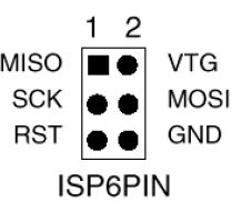 ISPs typically use a six-pin connector (2x3). It's not always easy to
figure out which end is which, so use a multimeter in continuity mode
to figure out which pin is ground. Once you're sure, mark your connector
so you'll know which pin is pin 1 (MISO, the pin opposite ground).
ISPs typically use a six-pin connector (2x3). It's not always easy to
figure out which end is which, so use a multimeter in continuity mode
to figure out which pin is ground. Once you're sure, mark your connector
so you'll know which pin is pin 1 (MISO, the pin opposite ground).
Once you have your ISP pins straight, refer to your handy-dandy
Atmega328 pinout and connect power, ground, MOSI, MISO, SCK, and RST
to the appropriate Atmega pins.
All wired up? In the Arduino IDE, set Programmer to your ISP,
for instance, USBtinyISP or Arduino as ISP
Then use the Upload button to upload sketches.
If you prefer Arduino-mk instead of the IDE, add this to your Makefile:
ISP_PROG = usbtiny
(or whatever ISP you're using). Then type
make ispload
instead of
make upload
Once you have your FTDI or ISP working, then you can think about making
an even simpler circuit -- without the external clock and its associated
capacitors. But there are a couple of additional tricks to that.
Stay tuned for Part 2.
Tags: hardware, arduino, maker
[
15:44 Dec 09, 2017
More hardware |
permalink to this entry |
]
Mon, 04 Dec 2017
![[Raspberry Pi Zero W with LED]](http://shallowsky.com/blog/images/pi-no-headers.jpg) Are you interested in all things Raspberry Pi, or just curious about them?
Come join like-minded people this Thursday at 7pm for the inaugural meeting
of the Los Alamos Raspberry Pi club!
Are you interested in all things Raspberry Pi, or just curious about them?
Come join like-minded people this Thursday at 7pm for the inaugural meeting
of the Los Alamos Raspberry Pi club!
At Los Alamos Makers,
we've had the Coder Dojo for Teens going on for over a year now,
but there haven't been any comparable programs that welcomes adults.
Pi club is open to all ages.
The format will be similar to Coder Dojo: no lectures or formal
presentations, just a bunch of people with similar interests.
Bring a project you're working on, see what other people are working
on, ask questions, answer questions, trade ideas and share knowledge.
Bring your own Pi if you like, or try out one of the Pi 3 workstations
Los Alamos Makers has set up. (If you use one of the workstations there,
I recommend bringing a USB stick so you can save your work to take home.)
Although the group is officially for Raspberry Pi hacking, I'm sure
many attendees will interested in Arduino or other microcontrollers, or
Beaglebones or other tiny Linux computers; conversation and projects
along those lines will be welcome.
Beginners are welcome too. You don't have to own a Pi, know a resistor
from a capacitor, or know anything about programming. I've been asked
a few times about where an adult can learn to program. The Raspberry Pi
was originally introduced as a fun way to teach schoolchildren to
program computers, and it includes programming resources suitable to
all ages and abilities. If you want to learn programming on your own
laptop rather than a Raspberry Pi, we won't turn you away.
Raspberry Pi Club:
Thursdays, 7pm, at Los Alamos Makers, 3540 Orange Street (the old PEEC
location), Suite LV1 (the farthest door from the parking lot -- look
for the "elevated walkway" painted outside the door).
There's a Facebook event:
Raspberry Pi club
on Facebook. We have meetings scheduled for the next few Thursdays:
December 7, 14, and 21, and after that we'll decide based on interest.
Tags: maker, hardware, raspberry pi, programming, maker
[
10:44 Dec 04, 2017
More hardware |
permalink to this entry |
]