Homemade Arduino Part 1: Programming an Atmega328 on a Breadboard
There are lots of tutorials around for building an Arduino on a breadboard, using an Atmega328 (or the older 168) chip, a crystal, a few capacitors and resistors and a power supply. It's a fun project that every Arduino hacker should try at least once.
But while there are lots of instructions on how to wire up a breadboard Arduino, most instructions on how to program one are confusing and incomplete.
Of course, you can program your Atmega chip while it's in an Arduino, then unplug it from the Arduino's socket and move it to the breadboard. But what a hassle! It's so more convenient to leave the chip in the breadboard while you test new versions of the code. And you can, in two different ways: with FTDI, which uses the Arduino bootloader, or with an ISP, which doesn't.
Either way, start by downloading a good pinout diagram for the Atmega328 chip. I use this one: the Arduino ATmega328 Pinout from HobbyTronics, which is very compact yet does a good job of including both the mappings to Arduino digital and analog pins and the functions like RX, TX, MOSI and MISO you'll need for programming the chip.
Load Programs with FTDI
![[Circuit for Atmega328 on breadboard with FTDI friend]](http://shallowsky.com/blog/images/arduino/bare-atmega-breadboard-ftdi_bb.jpg) An FTDI board is a little trickier to wire than an ISP, but it's
less risky because it loads the code the same way an Arduino would,
so you don't overwrite the bootloader and you
can still put your chip back into an Arduino if things go wrong.
So let's start with FTDI.
An FTDI board is a little trickier to wire than an ISP, but it's
less risky because it loads the code the same way an Arduino would,
so you don't overwrite the bootloader and you
can still put your chip back into an Arduino if things go wrong.
So let's start with FTDI.
I use an Adafruit "FTDI Friend", but there are lots of similar FTDI boards from Sparkfun and other vendors. They have six outputs, but you'll need only five of those. Referring to your Atmega pinout, wire up power, ground, TX, and RX. For some FTDI boards you may need pullup resistors on the TX and RX lines; I didn't need them.
Now you have four pins connected. Wiring the reset line is more complicated because it requires a 0.1μF capacitor. A lot of tutorials don't mention the capacitor, but it didn't work for me without one. Connect from RTS on the FTDI board, through the 0.1μF cap, to the RST line.
A 0.1μF capacitor is an electrolytic cap with a positive and a negative lead, but the few online tutorials that even mention the capacitor don't bother to say which side is whick. I connected the FTDI friend to the cap's negative lead, and the positive lead to the Atmega chip, and it worked.
You may also need a pullup on that RST/RTS line: a resistor around 10kΩ from the RST pin 1 of the atmega chip to the 5v power line. Note: the Fritzing diagram here shows pullup resistors on RST, TX and RX. You may not need any of them.
Incidentally, RST stands for "reset", while RTS stands for "Ready To Send"; they're not meant as anagrams of each other. The remaining pin on the FTDI friend, CTS, is "Clear To Send" and isn't needed for an Arduino.
Once the wiring is ready, plug in the FTDI board, check to make sure
Port is set to whatever port the FTDI board registered,
and try uploading a program as if you were uploading to a normal Arduino Uno.
And cross your fingers. If it doesn't work, try fiddling with pullups
and capacitor values.
Load Programs with an ISP
![[Circuit for Atmega328 on breadboard with ISP]](http://shallowsky.com/blog/images/arduino/bare-atmega-breadboard-isp_bb.jpg) An In-System Programmer, or ISP, writes programs straight to the chip,
bypassing (and overwriting) the Arduino bootloader. You can also use
an ISP to burn a new bootloader and reprogram the fuses on your
Arduino, to change parameters like the clock rate. (More on that in Part 2.)
An In-System Programmer, or ISP, writes programs straight to the chip,
bypassing (and overwriting) the Arduino bootloader. You can also use
an ISP to burn a new bootloader and reprogram the fuses on your
Arduino, to change parameters like the clock rate. (More on that in Part 2.)
You can use an Arduino as an ISP, but it's somewhat unreliable and prone to unexplained errors. A dedicated ISP isn't expensive, is easier to wire and is more likely to work. A common type of ISP is called a "USBtinyISP", and you can buy one from vendors like Sparkfun or Adafruit, or search for usbtinyisp on sites like ebay or aliexpress.
Update: I've been curious about this flakiness: why does "Arduino as ISP" work fine for some people and utterly fail for others? One person I asked thought it had to do with the way Arduinos reset the RESET line whenever the serial port is opened: so RESET gets toggled at the wrong time as the bootloader code is being transferred. An alternate method that may get around this is Gammon Forum's Atmega bootloader programmer, which includes the bootloader bits as part of the code so it doesn't need to re-open the serial port. Someone else says a 10 uF capacitor between reset and ground should prevent that from happening; and another person says it should be a 100nF capacitor between RST on the programmer and RST on the AVR-chip plus a 10k pullup resistor, Most Arduino-as-ISP tutorials, including the official ones on arduino.cc, don't mention either capacitors or pullups, so that may explain why the method works for some people and not others.
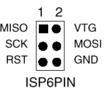 ISPs typically use a six-pin connector (2x3). It's not always easy to
figure out which end is which, so use a multimeter in continuity mode
to figure out which pin is ground. Once you're sure, mark your connector
so you'll know which pin is pin 1 (MISO, the pin opposite ground).
ISPs typically use a six-pin connector (2x3). It's not always easy to
figure out which end is which, so use a multimeter in continuity mode
to figure out which pin is ground. Once you're sure, mark your connector
so you'll know which pin is pin 1 (MISO, the pin opposite ground).
Once you have your ISP pins straight, refer to your handy-dandy Atmega328 pinout and connect power, ground, MOSI, MISO, SCK, and RST to the appropriate Atmega pins.
All wired up? In the Arduino IDE, set Programmer to your ISP, for instance, USBtinyISP or Arduino as ISP Then use the Upload button to upload sketches. If you prefer Arduino-mk instead of the IDE, add this to your Makefile:
ISP_PROG = usbtiny(or whatever ISP you're using). Then type
make ispload
instead of make upload
Once you have your FTDI or ISP working, then you can think about making an even simpler circuit -- without the external clock and its associated capacitors. But there are a couple of additional tricks to that. Stay tuned for Part 2.
[ 15:44 Dec 09, 2017 More hardware | permalink to this entry | ]