Time-lapse photography: a simple Arduino-driven camera intervalometer
![[Arduino intervalometer]](http://shallowsky.com/blog/images/hardware/img_6213-450.jpg) While testing my
automated critter
camera, I was getting lots of false positives caused by clouds
gathering and growing and then evaporating away. False positives
are annoying, but I discovered that it's fun watching the clouds grow
and change in all those photos
... which got me thinking about time-lapse photography.
While testing my
automated critter
camera, I was getting lots of false positives caused by clouds
gathering and growing and then evaporating away. False positives
are annoying, but I discovered that it's fun watching the clouds grow
and change in all those photos
... which got me thinking about time-lapse photography.
First, a disclaimer: it's easy and cheap to just buy an
intervalometer. Search for timer remote control
or intervalometer and you'll find plenty of options for
around $20-30. In fact, I ordered one.
But, hey, it's not here yet, and I'm impatient.
And I've always wanted to try controlling a camera from an Arduino.
This seemed like the perfect excuse.
Why an Arduino rather than a Raspberry Pi or BeagleBone? Just because it's simpler and cheaper, and this project doesn't need much compute power. But everything here should be applicable to any microcontroller.
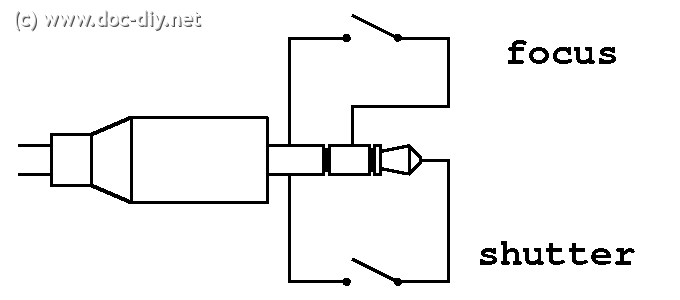
My Canon Rebel Xsi has a fairly simple wired remote control plug: a standard 2.5mm stereo phone plug. I say "standard" as though you can just walk into Radio Shack and buy one, but in fact it turned out to be surprisingly difficult, even when I was in Silicon Valley, to find them. Fortunately, I had found some, several years ago, and had cables already wired up waiting for an experiment.
The outside connector ("sleeve") of the plug is ground. Connecting ground to the middle ("ring") conductor makes the camera focus, like pressing the shutter button halfway; connecting ground to the center ("tip") conductor makes it take a picture. I have a wired cable release that I use for astronomy and spent a few minutes with an ohmmeter verifying what did what, but if you don't happen to have a cable release and a multimeter there are plenty of Canon remote control pinout diagrams on the web.
Now we need a way for the controller to connect one pin of the remote to another on command. There are ways to simulate that with transistors -- my Arduino-controlled robotic shark project did that. However, the shark was about a $40 toy, while my DSLR cost quite a bit more than that. While I did find several people on the web saying they'd used transistors with a DSLR with no ill effects, I found a lot more who were nervous about trying it. I decided I was one of the nervous ones.
The alternative to transistors is to use something like a relay. In a relay, voltage applied across one pair of contacts -- the signal from the controller -- creates a magnetic field that closes a switch and joins another pair of contacts -- the wires going to the camera's remote.
But there's a problem with relays: that magnetic field, when it collapses, can send a pulse of current back up the wire to the controller, possibly damaging it.
There's another alternative, though. An opto-isolator works like a relay but without the magnetic pulse problem. Instead of a magnetic field, it uses an LED (internally, inside the chip where you can't see it) and a photo sensor. I bought some opto-isolators a while back and had been looking for an excuse to try one. Actually two: I needed one for the focus pin and one for the shutter pin.
How do you choose which opto-isolator to use out of the gazillion options available in a components catalog? I don't know, but when I bought a selection of them a few years ago, it included a 4N25, 4N26 and 4N27, which seem to be popular and well documented, as well as a few other models that are so unpopular I couldn't even find a datasheet for them. So I went with the 4N25.
Wiring an opto-isolator is easy. You do need a resistor across the inputs (presumably because it's an LED). 380Ω is apparently a good value for the 4N25, but it's not critical. I didn't have any 380Ω but I had a bunch of 330Ω so that's what I used. The inputs (the signals from the Arduino) go between pins 1 and 2, with a resistor; the outputs (the wires to the camera remote plug) go between pins 4 and 5, as shown in the diagram on this Arduino and Opto-isolators discussion, except that I didn't use any pull-up resistor on the output.
Then you just need a simple Arduino program to drive the inputs. Apparently the camera wants to see a focus half-press before it gets the input to trigger the shutter, so I put in a slight delay there, and another delay while I "hold the shutter button down" before releasing both of them.
Here's some Arduino code to shoot a photo every ten seconds:
int focusPin = 6;
int shutterPin = 7;

int focusDelay = 50;
int shutterOpen = 100;
int betweenPictures = 10000;

void setup()
{
    pinMode(focusPin, OUTPUT);
    pinMode(shutterPin, OUTPUT);
}

void snapPhoto()
{
    digitalWrite(focusPin, HIGH);
    delay(focusDelay);
    digitalWrite(shutterPin, HIGH);
    delay(shutterOpen);
    digitalWrite(shutterPin, LOW);
    digitalWrite(focusPin, LOW);
}

void loop()
{
    delay(betweenPictures);
    snapPhoto();
}
Naturally, since then we haven't had any dramatic clouds, and the lightning storms have all been late at night after I went to bed. (I don't want to leave my nice camera out unattended in a rainstorm.) But my intervalometer seemed to work fine in short tests. Eventually I'll make some actual time-lapse movies ... but that will be a separate article.
[ 18:31 Jul 16, 2014 More hardware | permalink to this entry | ]