Driving two DC motors with a Raspberry Pi
![[Raspberry Pi robotic car]](http://shallowsky.com/blog/images/rpi/img_7522.jpg)
In my previous article about pulse-width modulation on Raspberry Pi, I mentioned that the reason I wanted PWM on several pins at once was to drive several motors, for a robotic car.
But there's more to driving motors than just PWM. The GPIO output pins of a Pi don't have either enough current or enough voltage to drive a motor. So you need to use a separate power supply to drive the motors, and do some sort of switching -- at minimum, a transistor or relay for each motor.
There are lots of motor driver chips. For Arduinos, "motor shields", and such things are starting to become available for the Pi as well. But motor shields are expensive, usually more than the Pi costs itself. If you're trying to outfit a robotics class, or to help low-income students build robots, it's not a great solution.
When I struggled with this problem for the Arduino, the solution I
eventually hit on was a
SN754410
H-bridge chip. For under $2, you get bidirectional control of two
DC motors. For each motor, you send input to the chip via a PWM line
and two directional control lines.
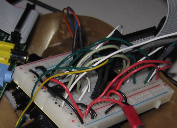
![[Snarl of wires driving a car with a Raspberry Pi]](http://shallowsky.com/blog/images/rpi/img_7514.jpg) The only problem is the snarl of wiring. One PWM and two direction
lines per motor is six wires, plus power for the chip's logic side,
power for the motors, and ground, and the three pins for a serial cable,
and you're talking a lot of wires to plug in.
Although this is all easy in comcept, it's also easy
to get a wire plugged in one spot over on the breadboard from where
it ought to be, and then nothing works.
The only problem is the snarl of wiring. One PWM and two direction
lines per motor is six wires, plus power for the chip's logic side,
power for the motors, and ground, and the three pins for a serial cable,
and you're talking a lot of wires to plug in.
Although this is all easy in comcept, it's also easy
to get a wire plugged in one spot over on the breadboard from where
it ought to be, and then nothing works.
I spent too much time making tables of what should get plugged into where. I ended up with a table like this:
| Pi connector pin | GPIO (BCM) | SN754410 pin |
|---|---|---|
| Pi 2 | 5V power | Breadboard bottom V+ row |
| Pi 18 | 24 | 1 (motor 1 PWM) |
| Pi 15 | 22 | 1 (motor 0 PWM) |
| Pi 24 | 8 (SPI CE0) | 4 (motor 1 direc 0) |
| Pi 26 | 7 (SPI CE1) | 14 (motor 1 direc 1) |
| Pi 25 | Gnd | Breadboard both grounds |
| Pi 19 | 10 (MOS1) | 3 (motor 0 direc 0) |
| Pi 21 | 9 (MOS0) | 13 (motor 0 direc 1) |
| motor 0 | 5, 11 | |
| motor 1 | 6, 12 |
One more thing: I found that I had to connect the chip's logic V+ (pin 2 on the SN754410) to the 5v pin on the RPi, not the 3.3V pin. The SN754410 is okay with 3.3V logic signals, but it seems to need a full 5V of power.
Programming it
The software control is a little trickier than it ought to be, too, because of the 2-wire control lines on each motor. With both lines high or both lines low, nothing moves. (Some motor driver chips distinguish between those two states: e.g. both low might be a brake, while both high lets the motor freewheel; but I haven't seen anything indicating the SN754410 makes any distinction.) Then set one line high, the other low, and the motor spins one way; reverse the lines, and the motor spins the other way. Assuming, of course, the PWM line is sending a signal.
Of course, you need RPI.GPIO version 0.5.2a or later to do any of this
PWM control. Get it via pip install --upgrade RPi.GPIO
-- the RPI.GPIO in Raspbian mis-reports its version and is really 0.5.1a.
Simple enough in concept. Okay, now try explaining that to beginning
programmers. No, thanks! So I wrote a PiMotor class in
Python that takes care of all those details. Initialize it with the pins
you want to use, then use calls like set_speed(s)
and stop(). It's on GitHub at
pimotors.py.
I put the H-bridge chip on a breadboard, wired up all the lines to the Pi and a lithium-polymer airplane battery, and (after several hours of head-banging while I found all the errors in my wiring), sure enough, I could get the motors to spin.
But one thing I found while wiring was that I couldn't always use the
GPIO lines I'd intended to use. The RPi has seemingly a lot of GPIO
lines -- but
nearly all of
the GPIO lines have other purposes, except I haven't found any
good explanation of what those uses are and how to know when they're
in use. I found that quite frequently, I'd try a
GPIO.setup(pin, GPIO.OUT) and get
"This channel is already in use". Sometimes GPIO.cleanup()
helped, and sometimes it didn't. None of this stuff has much
documentation, and I haven't found any IRC channel or mailing list
for discussing RPi GPIO. And of course, there's no relation between
the pin number on the header and the GPIO pin number. So I spent a lot
of time counting breadboard rows and correlating to a printout I'd made
of the RPi's GPIO socket.
Putting the circuit on a proto-board
Once I got it working, I realized how much I didn't relish the thought of ever doing it again -- like whenever I needed to unplug the motors from the Pi and use it for something else.
Fortunately, at some point I'd bought an Adafruit Pi Plate, sort of the RPi equivalent of Adafruit's Arduino ProtoShield. I love protoshields. I have a bunch of them, and I use them for all sorts of Arduino projects, so I'd bought the Pi Plate thinking it might come in handy some day. It's not quite like a protoshield, because it's expensive and heavy, loaded up with lots of pointless screw terminals. But you don't have to solder the screw terminals on; just solder the headers and you have a protoshield for your RPi on which you can put a mini breadboard and build your motor circuit.
I do wish, though, that Adafruit or someone made a simple, basic proto board PCB with headers for the Pi. No screw terminals, no extra parts, just the PCB and headers, to make it easy and cheap to swap between different RPi projects. The HobbyTronics Slice of Pi looks intriguing, but the GPIO pins it exposes don't seem to be the same ones exposed on the RPI's GPIO header. I'd be interested in hearing from anyone who's tried one of these.
![[Raspberry Pi motor circuitn]](http://shallowsky.com/blog/images/rpi/motors-pi-plate.jpg) Anyway, with the Pi Plate shield, my motor circuit looks much neater,
and I can unplug it from my RPi without fear that it'll mean
another half hour if I ever want to get the motors hooked up again.
I did have to change some of the pin assignments yet again, because
the Pi Plate doesn't expose all the GPIO pins available on the RPi header.
I ended up using 25, 23, 24 for the first motor, and 17, 21, 22 for
the second.
Anyway, with the Pi Plate shield, my motor circuit looks much neater,
and I can unplug it from my RPi without fear that it'll mean
another half hour if I ever want to get the motors hooked up again.
I did have to change some of the pin assignments yet again, because
the Pi Plate doesn't expose all the GPIO pins available on the RPi header.
I ended up using 25, 23, 24 for the first motor, and 17, 21, 22 for
the second.
I wanted to make a circuit diagram with Fritzing, but it turns out the Fritzing I have can't import part definitions like the one for Raspberry Pi, and the current Fritzing doesn't work on Debian Wheezy. So that'll have to wait. But here's a photo of my breadboarded circuit on the Pi Plate, and a link to my motor breadboarded circuit using a cable to the GPIO.
Kevin Mark tipped me off that Fritzing is quite easy to build under
Debian, if you first
apt-get install qt4-qmake libqt4-dev libboost1.49-dev
I had to add one more package to Kevin's list, libqt4-sql-sqlite,
or I got a lot of QSQLITE driver not loaded and other errors
on the terminal, and a dialog saying "Unable to find the following 114 parts"
followed by another dialog too big to fit on the screen with a list of
all the missing parts.
Once those packages are installed, download the Fritzing source tarball,
qmake, make, and sudo make install.
And my little car can go forward, spin around in both directions, and
then reverse! Now the trick will be to find some sensors I can use with
the pins remaining ...
[ 14:08 May 12, 2013 More hardware | permalink to this entry | ]