Shallow Thoughts : tags : raspberry pi
Akkana's Musings on Open Source Computing and Technology, Science, and Nature.
Thu, 27 Feb 2020
![[Raspberry Pi automatic plant waterer]](http://shallowsky.com/blog/images/plantwater/img_3632cT.jpg) An automatic plant watering system is a
project that's been on my back burner for years.
I'd like to be able to go on vacation and not worry about
whatever houseplant I'm fruitlessly nursing at the moment.
(I have the opposite of a green thumb -- I have very little luck
growing plants -- but I keep trying, and if nothing else, I can
make sure lack of watering isn't the problem.)
An automatic plant watering system is a
project that's been on my back burner for years.
I'd like to be able to go on vacation and not worry about
whatever houseplant I'm fruitlessly nursing at the moment.
(I have the opposite of a green thumb -- I have very little luck
growing plants -- but I keep trying, and if nothing else, I can
make sure lack of watering isn't the problem.)
I've had all the parts sitting around for quite some time,
and had tried them all individually,
but never seemed to make the time to put them all together.
Today's "Raspberry Pi Jam" at Los Alamos Makers seemed like
the ideal excuse.
Sensing Soil Moisture
First step: the moisture sensor. I used a little moisture sensor that
I found on eBay. It says "YL-38" on it. It has the typical forked thingie
you stick into the soil, connected to a little sensor board.
The board has four pins: power, ground, analog and digital outputs.
The digital output would be the easiest: there's a potentiometer on
the board that you can turn to adjust sensitivity, then you can read
the digital output pin directly from the Raspberry Pi.
But I had bigger plans: in addition to watering, I wanted to
keep track of how fast the soil dries out, and update a
web page so that I could check my plant's status from anywhere.
For that, I needed to read the analog pin.
Raspberry Pis don't have a way to read an analog input.
(An Arduino would have made this easier, but then reporting to a
web page would have been much more difficult.)
So I used an ADS1115 16-bit I2sup>C Analog to Digital
Converter board from Adafruit, along with
Adafruit's
ADS1x15 library. It's written for CircuitPython, but it works
fine in normal Python on Raspbian.
It's simple to use. Wire power, ground, SDA and SDC to the appropriate
Raspberry Pi pins (1, 6, 3 and 5 respectively). Connect the soil
sensor's analog output pin with A0 on the ADC. Then
# Initialize the ADC
i2c = busio.I2C(board.SCL, board.SDA)
ads = ADS.ADS1015(i2c)
adc0 = AnalogIn(ads, ADS.P0)

# Read a value
value = adc0.value
voltage = adc0.voltage
With the probe stuck into dry soil, it read around 26,500 value, 3.3 volts.
Damp soil was more like 14528, 1.816V.
Suspended in water, it was more like 11,000 value, 1.3V.
Driving a Water Pump
The pump also came from eBay. They're under $5; search for terms like
"Mini Submersible Water Pump 5V to 12V DC Aquarium Fountain Pump Micro Pump".
As far as driving it is concerned, treat it as a motor. Which means you
can't drive it directly from a Raspberry Pi pin: they don't generate
enough current to run a motor, and you risk damaging the Pi with back-EMF
when the motor stops.
![[Raspberry Pi automatic plant waterer wiring]](http://shallowsky.com/blog/images/plantwater/plant-watering_bbT.jpg) Instead, my go-to motor driver for small microcontroller projects is
a SN754410 SN754410 H-bridge chip. I've used them before for
driving
little cars with a Raspberry Pi or
with
an Arduino. In this case the wiring would be much simpler, because
there's only one motor and I only need to drive it in one direction.
That means I could hardwire the two motor direction pins, and the
only pin I needed to control from the Pi was the PWM motor speed pin.
The chip also needs a bunch of ground wires (which it uses as heat
sinks), a line to logic voltage (the Pi's 3.3V pin) and motor voltage
(since it's such a tiny motor, I'm driving it from the Pi's 5v power pin).
Instead, my go-to motor driver for small microcontroller projects is
a SN754410 SN754410 H-bridge chip. I've used them before for
driving
little cars with a Raspberry Pi or
with
an Arduino. In this case the wiring would be much simpler, because
there's only one motor and I only need to drive it in one direction.
That means I could hardwire the two motor direction pins, and the
only pin I needed to control from the Pi was the PWM motor speed pin.
The chip also needs a bunch of ground wires (which it uses as heat
sinks), a line to logic voltage (the Pi's 3.3V pin) and motor voltage
(since it's such a tiny motor, I'm driving it from the Pi's 5v power pin).
Here's the full wiring diagram.
Driving a single PWM pin is a lot simpler than the dual bidirectional
motor controllers I've used in other motor projects.
GPIO.setmode(GPIO.BCM)
GPIO.setup(23, GPIO.OUT)
pump = GPIO.PWM(PUMP_PIN, 50)
pump.start(0)

# Run the motor at 30% for 2 seconds, then stop.
pump.ChangeDutyCycle(30)
time.sleep(2)
pump.ChangeDutyCycle(0)
The rest was just putting together some logic: check the sensor,
and if it's too dry, pump some water -- but only a little, then wait a
while for the water to soak in -- and repeat.
Here's the full
plantwater.py
script.
I haven't added the website part yet, but the basic plant waterer
is ready to use -- and ready to demo at tonight's Raspberry Pi Jam.
Tags: raspberry pi, programming, python
[
13:50 Feb 27, 2020
More hardware |
permalink to this entry |
]
Wed, 12 Feb 2020
After writing a simple
kiosk
of rotating quotes and images,
I wanted to set up a Raspberry Pi to run the kiosk automatically,
without needing a keyboard or any on-site configuration.
The Raspbian Desktop: Too Hard to Configure
Unlike my usual Raspberry Pi hacks, the kiosk would need a monitor
and a window system. So instead of my usual Raspbian Lite install,
I opted for a full Raspbian desktop image.
Mistake. First, the Raspbian desktop is very slow. I intended to use
a Pi Zero W for the kiosk, but even on a Pi 3 the desktop was sluggish.
More important, the desktop is difficult to configure.
For instance, a kiosk needs to keep the screen on, so I needed to
disable the automatic screen blanking.
There are threads all over the web asking how to disable screen
blanking, with lots of solutions that no longer apply because Raspbian keeps
changing where desktop configuration files are stored.
Incredibly, the official Raspbian answer for how to disable screen
blanking in the desktop
— I can hardly type, I'm laughing so hard — is:
install xscreensaver,
which will then add a configuration option to turn off the screensaver.
(I actually tried that just to see if it would work,
but changed my mind when I saw the long list of
dependencies xscreensaver was going to pull in.)
I never did find a way to disable screen blanking, and after a few
hours of fighting with it, I decided it wasn't worth it. Setting up
Raspbian Lite is so much easier and I already knew how to do it.
If I didn't, Die Antwort has a nice guide,
Setup a Raspberry Pi to run a Web Browser in Kiosk Mode,
that uses my preferred window manager, Openbox. Here are my steps,
starting with a freshly burned Raspbian Lite SD card.
Set Up Raspbian Lite with Network and SSH
I wanted to use ssh on my home network while debugging, even though
the final kiosk won't need a network. The easiest way to do that
is to mount the first partition:
sudo mount /dev/sdX1 /mnt
(sdX is wherever the card shows up on your machine, e.g. sdB)
and create two files. First, an empty file named
ssh
touch /mnt/ssh
Second, create a file named wpa_supplicant.conf with the settings
for your local network:
ctrl_interface=DIR=/var/run/wpa_supplicant GROUP=netdev
update_config=1

network={
	ssid="MY-WIFI-SSID"
	psk="MY-WIFI-PASSWORD"
	priority=10
}
Then unmount that partition:
sudo umount /mnt
Copy the Kiosk Files into /home/pi
The second partition on a Raspbian card is the root filesystem,
including /home/pi, the pi user's home dictory. Mount
/dev/sdX2, copy your kiosk code into /home/pi, and
chown the code to the pi user. If you
don't know what that means or how to do that, you can skip this step
and load the code onto the Pi later once it's up and running, over the
network or via a USB stick.
Unmount the SD card and move it to the Raspberry Pi.
Raspbian First-boot Configuration
Boot the Pi with a monitor attached, log in as the pi user,
run sudo raspi-config, and:
- set the locale and keyboard,
- change the password for user Pi,
- in Boot Options, choose “Desktop / CLI” and “Console Autologin”
so the pi user will be logged in automatically.
So the installation won't become too bloated,
I like to create the file /etc/apt/apt.conf containing:
APT::Install-Recommends "false";
APT::Install-Suggests "false";
(That's the equivalent of the
--no-install-recommends in the
Die Antwort guide.)
Update the OS, and install the packages needed to run X,
the Openbox window manager, a terminal (I used xterm),
and a text editor (I used vim; if you're not familiar with Linux
text editors, pico is more beginner-friendly).
If you're in a hurry, you can skip the update and dist-upgrade
steps.
$ sudo apt update
$ sudo apt dist-upgrade
$ sudo apt install xserver-xorg x11-xserver-utils xinit openbox xterm vim
I was surprised how little time this took: even with all of the X
dependencies, the whole thing
took less than twenty minutes, compared to the several hours it had
taken to dist-upgrade all the packages on the full Raspbian
desktop.
Install any Kiosk-specific Packages
Install any packages you need to run your kiosk.
My kiosk was based on Python 3 and GTK 3:
sudo apt install python3-cairo python3-gi python3-gi-cairo \
         libgirepository-1.0-1 gir1.2-glib-2.0 python3-html2text
(This also pulled in gir1.2-atk-1.0, gir1.2-freedesktop,
gir1.2-gdkpixbuf-2.0, gir1.2-pango-1.0, and gir1.2-gtk-3.0,
but I don't think I had to specify any of them explicitly.)
Configure Openbox
Create the Openbox configuration directory:
mkdir -p .config/openbox
Create
.config/openbox/autostart containing:
# Disable screen saver/screen blanking/power management
xset s off
xset s noblank
xset -dpms

# Start a terminal
xterm &
Save the file, and test to make sure you can run X:
$ startx
You should see a black screen, a mouse pointer, and after a few seconds,
a small xterm window in the center of the screen. You can use the xterm
to fiddle with things you want to change, or you can right-click anywhere
outside the xterm window to get a menu that will let you exit X and
go back to the bare console.
Test Your Kiosk
With X running, you can run your kiosk command.
Don't change directories first; the pi user will be /home/pi
($HOME) after automatically logging in, so make sure you can run
from there.
For instance, I can run my kiosk with:
$HOME/src/scripts/quotekiosk.py $HOME/100-min-kiosk/slideshow/* $HOME/100-min-kiosk/quotes/*.html
Once the command works,
edit .config/openbox/autostart and add your
command at the end, after the xterm line, with an ampersand (&)
after it. Keep the xterm line in place
so you'll have a way to recover if things go wrong.
Configure X to Start When the Pi User Logs In
You've already set up the Pi user to be logged in automatically
when the machine boots, but pi needs to start X upon login.
Create the file .bash_profile containing:
[[ -z $DISPLAY && $XDG_VTNR -eq 1 ]] && startx
You should be ready to go.
Reboot, and the Pi should boot up in kiosk mode.
Run in a Loop
Everything working?
For extra security, you might want to tweak the autostart
file to run your kiosk in a loop. That way, even if the kiosk code
crashes for some reason, it will be restarted.
while :
do
    $HOME/src/scripts/quotekiosk.py $HOME/100-min-kiosk/slideshow/* $HOME/100-min-kiosk/quotes/*.html
done
Don't do this until after you've tested everything else; it's
hard to debug with the kiosk constantly popping up
on top of other windows.
Get Rid of that Pesky Cursor
You might also want to remove that annoying mouse pointer arrow in
the middle of the screen.
Editing that startx line you just added to .bash_profile:
[[ -z $DISPLAY && $XDG_VTNR -eq 1 ]] && startx -- -nocursor
This step comes last — because once you've disabled the cursor,
it will be difficult to use the machine interactively since you won't
be able to see where your mouse is. (If you need to make changes later,
you can ssh in from another machine, mount the Raspbian SD card on
another machine, or use Ctrl-Alt-F2 to switch
to a console window where you can edit files.)
... But It's Still Not Quite Hands-Off
The Pi is now set up to work automatically: just plug it in. The
problem was the monitor. Someone contributed a TV, but it turned out
to be a "smart TV", and it had its own ideas about what it would
connect to. Sometimes the HDMI ports worked, sometimes it refused to
display anything, and even when it worked, it randomly brightened and
dimmed so that the screen was often too dim to see.
So I contributed my old 20" monitor. Everything worked fine at the
demo the night before, and I handed it off to the people who were
going to be there early for setup. When I arrived at the Roundhouse
the next day, there was my monitor, displaying "No Signal". Apparently,
while setting it up, someone had bumped the monitor's "Input
Source" button; and of course no one there was up to the task of
diagnosing that difficult problem. And no one bothered to
call me and ask.
Once I arrived, I pressed the Source button a couple of times and the
kiosk display was up and running for the rest of the day. Sigh.
I can write kiosk software and set up Raspberry Pis; but
predicting potential issues non-technical users might encounter is
still beyond me.
Tags: raspberry pi
[
11:08 Feb 12, 2020
More tech |
permalink to this entry |
]
Sat, 08 Feb 2020
The LWV had a 100th anniversary celebration earlier this week.
In New Mexico, that included a big celebration at the Roundhouse. One of
our members has collected a series of fun facts that she calls
"100-Year Minutes". You can see them at
lwvnm.org.
She asked me if it would be possible to have them displayed somehow
during our display at the Roundhouse.
Of course! I said. "Easy, no problem!" I said.
Famous last words.
There are two parts: first, display randomly (or sequentially) chosen
quotes with large text in a fullscreen window. Second, set up a computer
(the obvious choice is a Raspberry Pi) run the kiosk automatically.
This article only covers the first part; I'll write about the
Raspberry
Pi setup separately.
A Simple Plaintext Kiosk Python Script
When I said "easy" and "no problem", I was imagining writing a
little Python program: get text, scale it to the screen, loop.
I figured the only hard part would be the scaling.
the quotes aren't all the same length, but I want them to be easy to read,
so I wanted each quote displayed in the largest font that would let the
quote fill the screen.
Indeed, for plaintext it was easy. Using GTK3 in Python, first you
set up a PangoCairo layout (Cairo is the way you draw in GTK3, Pango
is the font/text rendering library, and a layout is Pango's term
for a bunch of text to be rendered).
Start with a really big font size, ask PangoCairo how large the layout would
render, and if it's so big that it doesn't fit in the available space,
reduce the font size and try again.
It's not super elegant, but it's easy and it's fast enough.
It only took an hour or two for a working script, which you can see at
quotekiosk.py.
But some of the quotes had minor HTML formatting. GtkWebkit was
orphaned several years ago and was never available for Python 3; the
only Python 3 option I know of for displaying HTML is Qt5's
QtWebEngine, which is essentially a fully functioning browser window.
Which meant that it seeming made more sense to write the whole kiosk
as a web page, with the resizing code in JavaScript. I say "seemingly";
it didn't turn out that way.
JavaScript: Resizing Text to Fit Available Space
The hard part about using JavaScript was the text resizing, since
I couldn't use my PangoCairo resizing code.
Much web searching found lots of solutions that resize a single line
to fit the width of the screen, plus a lot of hand-waving
suggestions that didn't work.
I finally found a working solution in a StackOverflow thread:
Fit text perfectly inside a div (height and width) without affecting the size of the div.
The only one of the three solutions there that actually worked was
the jQuery one. It basically does the same thing my original Python
script did: check element.scrollHeight and if it overflows,
reduce the font size and try again.
I used the jquery version for a little while, but eventually rewrote it
to pure javascript so I wouldn't have to keep copying jquery-min.js around.
JS Timers on Slow Machines
There are two types of timers in Javascript:
setTimeout, which schedules something to run once N seconds from now, and
setInterval, which schedules something to run repeatedly every N seconds.
At first I thought I wanted setInterval, since I want
the kiosk to keep running, changing its quote every so often.
I coded that, and it worked okay on my laptop, but failed miserably
on the Raspberry Pi Zero W. The Pi, even with a lightweight browser
like gpreso (let alone chromium), takes so long to load a page and
go through the resize-and-check-height loop that by the time it has
finally displayed, it's about ready for the timer to fire again.
And because it takes longer to scale a big quote than a small one,
the longest quotes give you the shortest time to read them.
So I switched to setTimeout instead. Choose a quote (since JavaScript
makes it hard to read local files, I used Python to read all the
quotes in, turn them into a JSON list and write them out to a file
that I included in my JavaScript code), set the text color to the
background color so you can't see all the hacky resizing, run the
resize loop, set the color back to the foreground color, and only
then call setTimeout again:
function newquote() {
    // ... resizing and other slow stuff here

    setTimeout(newquote, 30000);
}

// Display the first page:
newquote();
That worked much better on the Raspberry Pi Zero W, so
I added code to resize images in a similar fashion, and added some fancy
CSS fade effects that it turned out the Pi was too slow to run, but it
looks nice on a modern x86 machine.
The full working kiosk code is
quotekioska>).
Memory Leaks in JavaScript's innerHTML
I ran it for several hours on my development machine and it looked
great. But when I copied it to the Pi, even after I turned off the
fades (which looked jerky and terrible on the slow processor), it
only ran for ten or fifteen minutes, then crashed. Every time.
I tried it in several browsers, but they all crashed after running a while.
The obvious culprit, since it ran fine for a while then crashed,
was a memory leak. The next step was to make a minimal test case.
I'm using innerHTML to change
the kiosk content, because it's the only way I know of to parse and
insert a snippet of HTML that may or may not contain paragraphs and
other nodes. This little test page was enough to show the effect:
<h1>innerHTML Leak</h1>

<p id="thecontent">
</p>

<script type="text/javascript">
var i = 0;
function changeContent() {
    var s = "Now we're at number " + i;
    document.getElementById("thecontent").innerHTML = s;
    i += 1;

    setTimeout(changeContent, 2000);
}

changeContent();
</script>
Chromium has a nice performance recording tool that can show
you memory leaks. (Firefox doesn't seem to have an equivalent, alas.)
![[Chrome performance graph showing innerHTML node leak]](http://shallowsky.com/blog/images/screenshots/inner-html-memleakT.jpg) To test a leak, go to More Tools > Developer Tools
and choose the Performance tab. Load your test page,
then click the Record button. Run it for a while, like a couple
of minutes, then stop it and you'll see a graph like this (click on
the image for a full-size version).
To test a leak, go to More Tools > Developer Tools
and choose the Performance tab. Load your test page,
then click the Record button. Run it for a while, like a couple
of minutes, then stop it and you'll see a graph like this (click on
the image for a full-size version).
Both the green line, Nodes, and the blue line, JS Heap,
are going up. But if you run it for longer, say, ten minutes, the
garbage collector eventually runs and the JS Heap line
drops back down. The Nodes line never does:
the node count just continues going up and up and up no matter how
long you run it.
So it looks like that's the culprit: setting innerHTML
adds a new node (or several) each time you call it, and those nodes are
never garbage collected. No wonder it couldn't run for long on the
poor Raspberry Pi Zero with 512Gb RAM (the Pi 3 with 1Gb didn't fare
much better).
It's weird that all browsers would have the same memory leak; maybe
something about the definition of innerHTML causes it.
I'm not enough of a Javascript expert to know, and the experts I
was able to find didn't seem to know anything about either why it
happened, or how to work around it.
Python html2text
So I gave up on JavaScript and
went back to my original Python text kiosk program.
After reading in an HTML snippet, I used the Python html2text
module to convert the snippet to text, then displayed it.
I added image resizing using GdkPixbuf and I was good to go.
quotekiosk.py
ran just fine throughout the centennial party,
and no one complained about the formatting not being
fancy enough. A happy ending, complete with cake and lemonade.
But I'm still curious about that JavaScript
leak, and whether there's a way to work around it. Anybody know?
Tags: programming, raspberry pi, python, javascript
[
18:48 Feb 08, 2020
More tech/web |
permalink to this entry |
]
Sun, 03 Nov 2019
I was planning to teach a class on Raspberry Pis, and I wanted to
start with the standard Raspbian image, update it, and add some
programs like GIMP that we'd use in the class. And I wanted to do
that just once, before burning the image to a bunch of different SD cards.
Is there a way to do that on my regular Linux box, with its nice
fast processor and disk?
Why yes, there is, and it's pretty easy. But there are a lot
of unclear or misleading tutorials out there, so I hope this is
a bit simpler and easier to follow.
I got most of this from a tutorial that no longer seems to be available
(but I'll include the link in case it comes back):
Solar Staker/RPI Image/Creation.
I've tested this on Ubuntu 19.10, Debian Stretch and Buster; the
instructions should be pretty general except for the name of the
loopback mount. Commands you type are in bold;
the rest is the output you should see. $ is your normal shell
prompt and # is a root prompt.
Required Packages
You'll need kpartx, qemu and some supporting packages.
On Debian or Ubuntu:
$ sudo apt install kpartx qemu binfmt-support qemu-user-static
You've probably already
downloaded
a Raspbian SD card image.
Set Up the Loopback Devices
kpartx can read the Raspbian ISO image and split it into the two
filesystems it would have if you wrote it to an SD card.
It turns the filesystems into loopback devices you can mount
like regular filesystems.
$ sudo kpartx -av 2019-09-26-raspbian-buster-lite.img
add map loop10p1 (253:1): 0 524288 linear 7:10 8192
add map loop10p2 (253:2): 0 3858432 linear 7:10 532480
Make a note of those loopback device names. They may not always
be loop10p1 and loop10p2, but they'll probably always end in
1 and 2. 1 is the Raspbian /boot filesystem, 2 is the Raspbian root.
(Optional) Check and Possibly Resize the Raspbian Filesystem
Make sure that the Raspbian filesystem is intact, and that it's a
reasonable size.
In practice, I didn't find this made any difference (everything was
fine to begin with), but it doesn't hurt to make sure.
$ sudo e2fsck -f /dev/mapper/loop10p2
e2fsck 1.45.3 (14-Jul-2019)
Pass 1: Checking inodes, blocks, and sizes
Pass 2: Checking directory structure
Pass 3: Checking directory connectivity
Pass 4: Checking reference counts
Pass 5: Checking group summary information
rootfs: 44367/120720 files (0.3$ non-contiguous), 292014/482304 blocks

$ sudo resize2fs /dev/mapper/loop10p2
resize2fs 1.45.3 (14-Jul-2019)
The filesystem is already 482304 (4k) blocks long.  Nothing to do!
Mount the Loopback Filesystems
You're ready to mount the two filesystems.
A Raspbian SD card image contains two filesystems.
Partition 1 is a small vfat /boot
filesystem containing the kernel and some other files it needs for
booting, plus the two important configuration files cmdline.txt
and config.txt.
Partition 2 is the Raspbian root filesystem in ext4 format.
The Raspbian root includes an empty /boot directory; mount
the root first, then mount the Raspbian boot partition on
Raspbian's /boot:
$ sudo mkdir /mnt/pi_image
$ sudo mount /dev/mapper/loop10p2 /mnt/pi_image
$ sudo mount /dev/mapper/loop10p1 /mnt/pi_image/boot
Prepare for Chroot
You're going to chroot to the Raspbian filesystem.
Chroot limits the filesystem you can access, so when you type /,
instead of your host filesystem's / you'll see the root of the
Raspbian filesystem, /mnt/pi_image. That means you
won't have access to your host system's /usr/bin, any more.
But qemu needs /usr/bin/qemu-arm-static to be able to emulate ARM
binaries in user mode. So copy that to the Raspbian filesystem so
you'll still be able to access it after the chroot:
$ sudo cp /usr/bin/qemu-arm-static /mnt/pi_image/usr/bin
Chroot to the Raspbian System
$ sudo chroot /mnt/pi_image /bin/bash
root:/#
Now you're running in Raspbian's root filesystem. All the binaries in
your path (e.g. /bin/ls, /bin/bash) are ARM binaries,
but if you try to run them, qemu will see qemu-arm-static and
run the program as though you're on an actual Raspberry Pi.
Run Stuff!
Now you can run Raspbian commands.
# file /bin/ls
/bin/ls: ELF 32-bit LSB executable, ARM, EABI5 version 1 (SYSV), dynamically linked, interpreter /lib/ld-linux-armhf.so.3, for GNU/Linux 3.2.0, BuildID[sha1]=67a394390830ea3ab4e83b5811c66fea9784ee69, stripped
#
# /bin/ls
bin   dev  home  lost+found  mnt  proc	run   srv  tmp	var
boot  etc  lib	 media	     opt  root	sbin  sys  usr

# file /bin/cat
/bin/cat: ELF 32-bit LSB executable, ARM, EABI5 version 1 (SYSV), dynamically linked, interpreter /lib/ld-linux-armhf.so.3, for GNU/Linux 3.2.0, BuildID[sha1]=2239a192f2f277bd1a4892e39a41eba97266b91f, stripped
#
# cat /etc/issue
Raspbian GNU/Linux 10 \n \l
You can even install packages or update the whole system:
# apt update
Get:1 http://raspbian.raspberrypi.org/raspbian buster InRelease [15.0 kB]
Get:2 http://archive.raspberrypi.org/debian buster InRelease [25.2 kB]
Get:3 http://raspbian.raspberrypi.org/raspbian buster/main armhf Packages [13.0 MB]
Get:4 http://archive.raspberrypi.org/debian buster/main armhf Packages [259 kB]
Fetched 13.3 MB in 20s (652 kB/s)
Reading package lists... Done

# apt dist-upgrade
Reading package lists... Done
Building dependency tree
Reading state information... Done
Calculating upgrade... Done
The following NEW packages will be installed:
  busybox initramfs-tools initramfs-tools-core klibc-utils libklibc linux-base
  pigz
The following packages will be upgraded:
  dhcpcd5 e2fsprogs file firmware-atheros firmware-brcm80211 firmware-libertas
  firmware-misc-nonfree firmware-realtek libcom-err2 libext2fs2 libmagic-mgc
  libmagic1 libraspberrypi-bin libraspberrypi-dev libraspberrypi-doc
  libraspberrypi0 libss2 libssl1.1 libxml2 libxmuu1 openssh-client
  openssh-server openssh-sftp-server openssl raspberrypi-bootloader
  raspberrypi-kernel raspi-config rpi-eeprom rpi-eeprom-images ssh sudo
  wpasupplicant
32 upgraded, 7 newly installed, 0 to remove and 0 not upgraded.
Need to get 133 MB of archives.
After this operation, 3192 kB of additional disk space will be used.
Do you want to continue? [Y/n]
Pretty neat! Although you're not actually running Raspbian, you can
run Raspbian executables with the Raspbian root filesystem mounted
as though you were actually running on your Raspberry Pi.
Cleaning Up
When you're done with the chroot, just exit that shell (Ctrl-D
or exit).
If you want to undo everything else afterward:
$ sudo rm /mnt/pi_image/usr/bin/qemu-arm-static

$ sudo umount /mnt/pi_image/boot
$ sudo umount /mnt/pi_image

$ sudo kpartx -dv /dev/loop0
$ sudo losetup -d /dev/loop0

$ sudo rmdir /mnt/pi_image
Limitations
Keep in mind you're not really running Raspbian.
You never booted the Raspbian kernel, and you can't test things
that depend on Raspbian's init system, like whether networking works,
let alone running the Raspbian X desktop or accessing GPIO pins.
This is an ARM emulator, not a Raspberry Pi emulator.
More details
If you want to read more about qemu user mode and how it lets you run
binaries from other architectures, I recommend these links:
Tags: linux, raspberry pi, virtualization, QEMU
[
16:14 Nov 03, 2019
More linux |
permalink to this entry |
]
Tue, 12 Feb 2019
![[Weather station]](http://shallowsky.com/blog/images/SDR-ambient/img_3178.jpg) A while back, Dave ordered a weather station.
His research pointed to the
Ambient Weather WS-2000 as the best bang for the buck as far as accuracy
(after it's calibrated, which is a time consuming and exacting process
where you compare readings to a known-good mercury thermometer, a process
that I suspect most weather station owners don't bother with).
A while back, Dave ordered a weather station.
His research pointed to the
Ambient Weather WS-2000 as the best bang for the buck as far as accuracy
(after it's calibrated, which is a time consuming and exacting process
where you compare readings to a known-good mercury thermometer, a process
that I suspect most weather station owners don't bother with).
It comes with a little 7" display console that sits indoors and
reads the radio signal from the outside station as well as a second
thermometer inside, then displays all the current weather data.
It also uses wi-fi to report the data upstream to Ambient and,
optionally, to a weather site such as Wunderground.
(Which we did for a while, but now Wunderground is closing off
their public API, so why give them data if they're not going to
make it easy to share it?)
![[Weather station console]](http://shallowsky.com/blog/images/SDR-ambient/img_3179.jpg) Having the console readout and the Ambient "dashboard" is all very
nice, but of course, being a data geek, I wanted a way to get the data
myself, so I could plot it, save it or otherwise process it. And
that's where Ambient falls short. The console, though it's already
talking on wi-fi, gives you no way to get the data. They sell a
separate unit called an "Observer" that provides a web page you
can scrape, and we actually ordered one, but it turned out to be
buggy and difficult to use, giving numbers that were substantially
different from what the console showed, and randomly failing to answer,
and we ended up returning the observer for a refund.
Having the console readout and the Ambient "dashboard" is all very
nice, but of course, being a data geek, I wanted a way to get the data
myself, so I could plot it, save it or otherwise process it. And
that's where Ambient falls short. The console, though it's already
talking on wi-fi, gives you no way to get the data. They sell a
separate unit called an "Observer" that provides a web page you
can scrape, and we actually ordered one, but it turned out to be
buggy and difficult to use, giving numbers that were substantially
different from what the console showed, and randomly failing to answer,
and we ended up returning the observer for a refund.
The other way of getting the data is online. Ambient provides an API
you can use for that purpose, if you email them for a key. It
mostly works, but it sometimes lags considerably behind real time, and
it seems crazy to have to beg for a key and then get data from a
company website that originated in our own backyard.
What I really wanted to do was read the signal from the weather
station directly. I'd planned for ages to look into how to do that,
but I'm a complete newbie to software defined radio and wasn't
sure where to start. Then one day I noticed an SDR discussion
on the #raspberrypi IRC channel on Freenode where I often hang out.
I jumped in, asked some questions, and got pointed in the right direction
and referred to the friendly and helpful #rtlsdr Freenode channel.
An Inexpensive SDR Dongle
Update:
Take everything that follows with a grain of salt.
I got it working, everything was great -- then when I tried it the
very next day after I wrote the article, none of it worked. At all.
The SDR dongle no longer saw anything from the station, even though
the station was clearly still sending to the console.
I never did get it working reliably, nor did I ever find out what
the problem was, and in the end I gave up.
Occasionally the dongle will see the weather station's output,
but most of the time it doesn't. It might be a temperature sensitivity
issue (though the dongle I bought is supposed to be temperature compensated).
Or maybe it's gremlins. Whatever it is, be warned that although the
information below might get you started, it probably won't get you
a reliably working SDR solution. I wish I knew the answer.
![[Raspberry Pi with SDR dongle]](http://shallowsky.com/blog/images/SDR-ambient/img_3175.jpg) On the experts' advice, I ordered a
RTL-SDR
Blog R820T2 RTL2832U 1PPM TCXO SMA Software Defined Radio with 2x
Telescopic Antennas on Amazon. This dongle apparently has better
temperature compensation than cheaper alternatives, it came with
a couple of different antenna options, and I was told it should
work well with Linux using a program called
rtl_433.
On the experts' advice, I ordered a
RTL-SDR
Blog R820T2 RTL2832U 1PPM TCXO SMA Software Defined Radio with 2x
Telescopic Antennas on Amazon. This dongle apparently has better
temperature compensation than cheaper alternatives, it came with
a couple of different antenna options, and I was told it should
work well with Linux using a program called
rtl_433.
Indeed it did. The command to monitor the weather station is
rtl_433 -f 915M
rtl_433 already knows the protocol for the WS-2000,
so I didn't even need to do any decoding or reverse engineering;
it produces a running account of the periodic signals being
broadcast from the station. rtl_433 also helpfully offers -F json
and -F csv options, along with a few other formats.
What a great program!
JSON turned out to be the easiest for me to use; initially I thought
CSV would be more compact, but rtl_433's CSV format includes fields
for every possible quantity a weather station could ever broadcast.
When you think about it, that makes sense: once you're outputting
CSV you can't add a new field in mid-stream, so you'd better be
ready for anything. JSON, on the other hand, lets you report
just whatever the weather station reports, and it's easy to parse
from nearly any programming language.
Testing the SDR Dongle
Full disclosure: at first, rtl_433 -f 915M wasn't showing
me anything and I still don't know why. Maybe I had a loose connection
on the antenna, or maybe I got unlucky and the weather station picked
the exact wrong time to take a vacation. But while I was testing,
I found another program that was very helpful in testing whether
my SDR dongle was working: rtl_fm, which plays radio stations.
The only trick is finding the right arguments,
since the example from the man page just played static.
Here's what worked for me:
rtl_fm -f 101.1M -M fm -g 20 -s 200k -A fast -r 32k -l 0 -E deemp | play -r 32k -t raw -e s -b 16 -c 1 -V1 -
That command plays the 101.1 FM radio station. (I had to do a web search
to give me some frequencies of local radio stations; it's been
a long time since I listened to normal radio.)
Once I knew the dongle was working, I needed to verify what frequency
the weather station was using for its broadcasts.
What I really wanted was something that would scan frequencies around
915M and tell me what it found. Everyone kept pointing me to a program
called Gqrx. But it turns out Gqrx on Linux requires PulseAudio and
absolutely refuses to work or install without it, even if you have no
interest in playing audio. I didn't want to break my system's sound
(I've never managed to get sound working reliably under PulseAudio),
and although it's supposedly possible to build Gqrx without Pulse,
it's a difficult build: I saw plenty of horror stories, and it
requires Boost, always a sign that a build will be problematic.
I fiddled with it a little but decided it wasn't a good time investment.
I eventually found a scanner that worked:
RTLSDR-Scanner.
It let me set limiting frequencies and scan between them, and by
setting it to accumulate, I was able to verify that indeed, the
weather station (or something else!) was sending a signal on 915 MHz.
I guess by then, the original problem had fixed itself, and after that,
rtl_433 started showing me signals from the weather station.
It's not super polished, but it's the only scanner I've found that
works without requiring PulseAudio.
That Puzzling Rainfall Number
One mystery remained to be solved. The JSON I was getting from the
weather station looked like this (I've reformatted it for readablility):
{
    "time" : "2019-01-11 11:50:12",
    "model" : "Fine Offset WH65B",
    "id" : 60,
    "temperature_C" : 2.200,
    "humidity" : 94,
    "wind_dir_deg" : 316,
    "wind_speed_ms" : 0.064,
    "gust_speed_ms" : 0.510,
    "rainfall_mm" : 90.678,
    "uv" : 324,
    "uvi" : 0,
    "light_lux" : 19344.000,
     "battery" : "OK",
    "mic" : "CRC"
}
This on a day when it hadn't rained in ages. What was up with that
"rainfall_mm" : 90.678 ?
I asked on the rtl_433 list and got a prompt and helpful answer:
it's a cumulative number, since some unspecified time in the past
(possibly the last time the battery was changed?) So as long as
I make a note of the rainfall_mm number, any change in
that number means new rainfall.
This being a snowy winter, I haven't been able to test that yet:
the WS-2000 doesn't measure snowfall unless some snow happens to melt
in the rain cup.
Some of the other numbers, like uv and uvi, are in mysterious unknown
units and sometimes give results that make no sense (why doesn't
uv go to zero at night? You're telling me that there's that much UV
in starlight?), but I already knew that was an issue with the Ambient.
It's not rtl_433's fault.
I notice that the numbers are often a bit different from what the
Ambient API reports; apparently they do some massaging of the numbers,
and the console has its own adjustment factors too.
We'll have to do some more calibration with a mercury thermometer
to see which set of numbers is right.
Anyway, cool stuff! It took no time at all to write a simple client
for my WatchWeather
web app that runs rtl_433 and monitors the JSON output.
I already had WatchWeather clients collecting reports from
Raspberry Pi Zero Ws sitting at various places in the house with
temperature/humidity sensors attached; and now my WatchWeather page
can include the weather station itself.
Meanwhile, we donated another
weather
station to the Los Alamos Nature Center,
though it doesn't have the SDR dongle, just the normal Ambient console
reporting to Wunderground.
Tags: SDR, weather, programming, raspberry pi
[
13:20 Feb 12, 2019
More tech |
permalink to this entry |
]
Mon, 03 Sep 2018
Continuing the discussion of USB networking from a Raspberry Pi Zero
or Zero W (Part
1: Configuring an Ethernet Gadget and
Part
2: Routing to the Outside World): You've connected your Pi Zero to another
Linux computer, which I'll call the gateway computer, via a micro-USB cable.
Configuring the Pi end is easy. Configuring the gateway end is easy as
long as you know the interface name that corresponds to the gadget.
ip link gave a list of several networking devices;
on my laptop right now they include lo, enp3s0, wlp2s0 and enp0s20u1.
How do you tell which one is the Pi Gadget?
When I tested it on another machine, it showed up as
enp0s26u1u1i1. Even aside from my wanting to script it, it's
tough for a beginner to guess which interface is the right one.
Try dmesg
Sometimes you can tell by inspecting the output of dmesg | tail.
If you run dmesg shortly after you initialized the gadget (either by
plugging the USB cable into the gateway computer, you'll see some
lines like:
[  639.301065] cdc_ether 3-1:1.0 enp0s20u1: renamed from usb0
[ 9458.218049] usb 3-1: USB disconnect, device number 3
[ 9458.218169] cdc_ether 3-1:1.0 enp0s20u1: unregister 'cdc_ether' usb-0000:00:14.0-1, CDC Ethernet Device
[ 9462.363485] usb 3-1: new high-speed USB device number 4 using xhci_hcd
[ 9462.504635] usb 3-1: New USB device found, idVendor=0525, idProduct=a4a2
[ 9462.504642] usb 3-1: New USB device strings: Mfr=1, Product=2, SerialNumber=0
[ 9462.504647] usb 3-1: Product: RNDIS/Ethernet Gadget
[ 9462.504660] usb 3-1: Manufacturer: Linux 4.14.50+ with 20980000.usb
[ 9462.506242] cdc_ether 3-1:1.0 usb0: register 'cdc_ether' at usb-0000:00:14.0-1, CDC Ethernet Device, f2:df:cf:71:b9:92
[ 9462.523189] cdc_ether 3-1:1.0 enp0s20u1: renamed from usb0
(Aside: whose bright idea was it that it would be a good idea to rename
usb0 to enp0s26u1u1i1, or wlan0 to wlp2s0? I'm curious exactly who finds
their task easier with the name enp0s26u1u1i1 than with usb0. It
certainly complicated all sorts of network scripts and howtos when the
name wlan0 went away.)
Anyway, from inspecting that dmesg output you can probably figure out
the name of your gadget interface. But it would be nice to have
something more deterministic, something that could be used from a script.
My goal was to have a shell function in my .zshrc, so I could type
pigadget and have it set everything up automatically.
How to do that?
A More Deterministic Way
First, the name starts with en, meaning it's an ethernet interface,
as opposed to wi-fi, loopback, or various other types of networking
interface. My laptop also has a built-in ethernet interface,
enp3s0, as well as lo0,
the loopback or "localhost" interface, and wlp2s0,
the wi-fi chip, the one that used to be called wlan0.
Second, it has a 'u' in the name. USB ethernet interfaces start with
en and then add suffixes to enumerate all the hubs involved.
So the number of 'u's in the name tells you how many hubs are involved;
that enp0s26u1u1i1 I saw on my desktop had two hubs in the way,
the computer's internal USB hub plus the external one sitting on my desk.
So if you have no USB ethernet interfaces on your computer,
looking for an interface name that starts with 'en' and has at least
one 'u' would be enough. But if you have USB ethernet, that
won't work so well.
Using the MAC Address
You can get some useful information from the MAC address,
called "link/ether" in the ip link output.
In this case, it's f2:df:cf:71:b9:92, but -- whoops! --
the next time I rebooted the Pi, it became ba:d9:9c:79:c0:ea.
The address turns out to be
randomly
generated and will be different every time. It is possible to set
it to a fixed value, and that thread has some suggestions on how,
but I think they're out of date, since they reference a kernel module
called g_ether whereas the module on my updated Raspbian
Stretch is called cdc_ether. I haven't tried.
Anyway, random or not, the MAC address also has one useful property:
the first octet (f2 in my first example)
will always have the '2' bit set, as an indicator that it's a "locally
administered" MAC address rather than one that's globally unique.
See the Wikipedia page
on MAC addressing for details on the structure of MAC addresses.
Both f2 (11110010 in binary) and ba (10111010 binary) have the
2 (00000010) bit set.
No physical networking device, like a USB ethernet dongle, should have
that bit set; physical devices have MAC addresses that indicate what
company makes them. For instance, Raspberry Pis with networking, like
the Pi 3 or Pi Zero W, have interfaces that start with b8:27:eb.
Note the 2 bit isn't set in b8.
Most people won't have any USB ethernet devices connected that have
the "locally administered" bit set. So it's a fairly good test for
a USB ethernet gadget.
Turning That Into a Shell Script
So how do we package that into a pipeline so the shell -- zsh, bash or
whatever -- can check whether that 2 bit is set?
First, use ip -o link to print out information about all
network interfaces on the system.
But really you only need the ones starting with en and
containing a u. Splitting out the u isn't easy at this
point -- you can check for it later -- but you can at least limit it to lines
that have en after a colon-space. That gives output like:
$ ip -o link | grep ": en"
5: enp3s0:  mtu 1500 qdisc pfifo_fast state DOWN mode DEFAULT group default qlen 1000\    link/ether 74:d0:2b:71:7a:3e brd ff:ff:ff:ff:ff:ff
8: enp0s20u1:  mtu 1500 qdisc noop state DOWN mode DEFAULT group default qlen 1000\    link/ether f2:df:cf:71:b9:92 brd ff:ff:ff:ff:ff:ff
Within that, you only need two pieces: the interface name (the second word)
and the MAC address (the 17th word). Awk is a good tool for picking
particular words out of an output line:
$ ip -o link | grep ': en' | awk '{print $2, $17}'
enp3s0: 74:d0:2b:71:7a:3e
enp0s20u1: f2:df:cf:71:b9:92
The next part is harder: you have to get the shell to loop over those
output lines, split them into the interface name and the MAC address,
then split off the second character of the MAC address and test it
as a hexadecimal number to see if the '2' bit is set. I suspected that
this would be the time to give up and write a Python script, but no,
it turns out zsh and even bash can test bits:
ip -o link | grep en | awk '{print $2, $17}' | \
    while read -r iff mac; do
        # LON is a numeric variable containing the digit we care about.
        # The "let" is required so LON will be a numeric variable,
        # otherwise it's a string and the bitwise test fails.
        let LON=0x$(echo $mac | sed -e 's/:.*//' -e 's/.//')

        # Is the 2 bit set? Meaning it's a locally administered MAC
        if ((($LON & 0x2) != 0)); then
            echo "Bit is set, $iff is the interface"
        fi
    done
Pretty neat! So now we just need to package it up into a shell function
and do something useful with $iff when you find one with the bit set:
namely, break out of the loop, call ip a add and
ip link set to enable networking to the Raspberry Pi
gadget, and enable routing so the Pi will be able to get to
networks outside this one. Here's the final function:
# Set up a Linux box to talk to a Pi0 using USB gadget on 192.168.0.7:
pigadget() {
    iface=''

    ip -o link | grep en | awk '{print $2, $17}' | \
        while read -r iff mac; do
            # LON is a numeric variable containing the digit we care about.
            # The "let" is required so zsh will know it's numeric,
            # otherwise the bitwise test will fail.
            let LON=0x$(echo $mac | sed -e 's/:.*//' -e 's/.//')

            # Is the 2 bit set? Meaning it's a locally administered MAC
            if ((($LON & 0x2) != 0)); then
                iface=$(echo $iff | sed 's/:.*//')
                break
            fi
        done

    if [[ x$iface == x ]]; then
        echo "No locally administered en interface:"
        ip a | egrep '^[0-9]:'
        echo Bailing.
        return
    fi

    sudo ip a add 192.168.7.1/24 dev $iface
    sudo ip link set dev $iface up

    # Enable routing so the gadget can get to the outside world:
    sudo sh -c 'echo 1 > /proc/sys/net/ipv4/ip_forward'
    sudo iptables -t nat -A POSTROUTING -o eth0 -j MASQUERADE
}
Tags: raspberry pi, linux, networking
[
18:41 Sep 03, 2018
More linux |
permalink to this entry |
]
Fri, 31 Aug 2018
I wrote some time ago about how to use a
Raspberry
Pi over USB as an "Ethernet Gadget". It's a handy way to talk to
a headless Pi Zero or Zero W if you're somewhere where it doesn't already
have a wi-fi network configured.
However, the setup I gave in that article doesn't offer a way for the
Pi Zero to talk to the outside world. The Pi is set up to use the
machine on the other end of the USB cable for routing and DNS, but that
doesn't help if the machine on the other end isn't acting as a router
or a DNS host.
A lot of the ethernet gadget tutorials I found online
explain how to do this on Mac and Windows, but it was tough to find
an example for Linux. The best I found was for Slackware,
How
to connect to the internet over USB from the Raspberry Pi Zero,
which should work on any Linux, not just Slackware.
Let's assume you have the Pi running as a gadget and you can talk to it,
as discussed in the previous article, so you've run:
sudo ip a add 192.168.7.1/24 dev enp0s20u1
sudo ip link set dev enp0s20u1 up
substituting your network number and the interface name that the Pi
created on your Linux machine, which you can find in
dmesg | tail or
ip link. (In Part 3
I'll talk more about how to find the right interface name
if it isn't obvious.)
At this point, the network is up and you should be able to ping the Pi
with the address you gave it, assuming you used a static IP:
ping 192.168.7.2
If that works, you can ssh to it, assuming you've enabled ssh.
But from the Pi's end, all it can see is your machine; it can't
get out to the wider world.
For that, you need to enable IP forwarding and masquerading:
sudo sh -c 'echo 1 > /proc/sys/net/ipv4/ip_forward'
sudo iptables -t nat -A POSTROUTING -o eth0 -j MASQUERADE
Now the Pi can route to the outside world, but it still doesn't have
DNS so it can't get any domain names. To test that, on the gateway machine
try pinging some well-known host:
$ ping -c 2 google.com
PING google.com (216.58.219.110) 56(84) bytes of data.
64 bytes from mia07s25-in-f14.1e100.net (216.58.219.110): icmp_seq=1 ttl=56 time=78.6 ms
64 bytes from mia07s25-in-f14.1e100.net (216.58.219.110): icmp_seq=2 ttl=56 time=78.7 ms

--- google.com ping statistics ---
2 packets transmitted, 2 received, 0% packet loss, time 1001ms
rtt min/avg/max/mdev = 78.646/78.678/78.710/0.032 ms
Take the IP address from that -- e.g. 216.58.219.110 -- then go to a shell
on the Pi and try ping -c 2 216.58.219.110, and you should
see a response.
DNS with a Public DNS Server
Now all you need is DNS. The easy way is to use one of the free DNS
services, like Google's 8.8.8.8. Edit /etc/resolv.conf and add
a line like
nameserver 8.8.8.8
and then try pinging some well-known hostname.
If it works, you can make that permanent by editing /etc/resolv.conf,
and adding this line:
name_servers=8.8.8.8
Otherwise you'll have to do it every time you boot.
Your Own DNS Server
But not everyone wants to use public nameservers like 8.8.8.8.
For one thing, there are privacy implications: it means you're telling
Google about every site you ever use for any reason.
Fortunately, there's an easy way around that, and you don't even
have to figure out how to configure bind/named. On the gateway box,
install dnsmasq, available through your distro's repositories.
It will use whatever nameserver you're already using on that machine,
and relay it to other machines like your Pi that need the information.
I didn't need to configure it at all; it worked right out of the box.
In the next article, Part 3:
more about those crazy interface names (why is it
enp0s20u1 on my laptop but enp0s26u1u1i1 on my desktop?),
how to identify which interface is the gadget by using its MAC,
and how to put it all together into a shell function so you can
set it up with one command.
Tags: raspberry pi, linux, networking
[
15:25 Aug 31, 2018
More linux |
permalink to this entry |
]
Sat, 17 Feb 2018
In the previous article I talked about
Multiplexing
input/output using shift registers for a music keyboard project.
I ended up with three CD4021 8-bit shift registers cascaded.
It worked; but I found that I was spending all my time in the
delays between polling each bit serially. I wanted a way to read
those bits faster. So I ordered some I/O expander chips.
![[Keyboard wired to Raspberry Pi with two MCP23017 port expanders]](http://shallowsky.com/blog/images/multiplex/img_1995.jpg) I/O expander, or port expander, chips take a lot of the hassle out of
multiplexing. Instead of writing code to read bits serially, you can use I2C.
Some chips also have built-in pullup resistors, so you don't need all
those extra wires for pullups or pulldowns.
There are lots of options, but two common chips are the MCP23017,
which controls 16 lines, and the MCP23008 and PCF8574p, which each
handle 8. I'll only discuss the MCP23017 here, because if eight is good,
surely sixteen is better! But the MCP23008 is basically the same thing
with fewer I/O lines.
I/O expander, or port expander, chips take a lot of the hassle out of
multiplexing. Instead of writing code to read bits serially, you can use I2C.
Some chips also have built-in pullup resistors, so you don't need all
those extra wires for pullups or pulldowns.
There are lots of options, but two common chips are the MCP23017,
which controls 16 lines, and the MCP23008 and PCF8574p, which each
handle 8. I'll only discuss the MCP23017 here, because if eight is good,
surely sixteen is better! But the MCP23008 is basically the same thing
with fewer I/O lines.
A good tutorial to get you started is
How
To Use A MCP23017 I2C Port Expander With The Raspberry Pi - 2013 Part 1
along
with part
2, Python and
part
3, reading input.
I'm not going to try to repeat what's in those tutorials, just
fill in some gaps I found. For instance,
I didn't find I needed sudo for all those I2C commands in Part 1
since my user is already in the i2c group.
Using Python smbus
Part 2 of that tutorial uses Python smbus, but it doesn't really
explain all the magic numbers it uses, so it wasn't obvious how to
generalize it when I added a second expander chip. It uses this code:
DEVICE = 0x20 # Device address (A0-A2)
IODIRA = 0x00 # Pin direction register
OLATA  = 0x14 # Register for outputs
GPIOA  = 0x12 # Register for inputs

# Set all GPA pins as outputs by setting
# all bits of IODIRA register to 0
bus.write_byte_data(DEVICE,IODIRA,0x00)

# Set output all 7 output bits to 0
bus.write_byte_data(DEVICE,OLATA,0)
DEVICE is the address on the I2C bus, the one you see with
i2cdetect -y 1 (20, initially).
IODIRA is the direction: when you call
bus.write_byte_data(DEVICE, IODIRA, 0x00)
you're saying that all eight bits in GPA should be used for output.
Zero specifies output, one input: so if you said
bus.write_byte_data(DEVICE, IODIRA, 0x1F)
you'd be specifying that you want to use the lowest five bits for output
and the upper three for input.
OLATA = 0x14 is the command to use when writing data:
bus.write_byte_data(DEVICE, OLATA, MyData)
means write data to the eight GPA pins. But what if you want to write to
the eight GPB pins instead? Then you'd use
OLATB  = 0x15
bus.write_byte_data(DEVICE, OLATB, MyData)
Likewise, if you want to read input from some of the GPB bits, use
GPIOB  = 0x13
val = bus.read_byte_data(DEVICE, GPIOB)
The MCP23017 even has internal pullup resistors you can enable:
GPPUA  = 0x0c    # Pullup resistor on GPA
GPPUB  = 0x0d    # Pullup resistor on GPB
bus.write_byte_data(DEVICE, GPPUB, inmaskB)
Here's a full example:
MCP23017.py
on GitHub.
Using WiringPi
You can also talk to an MCP23017 using the WiringPi library.
In that case, you don't set all the bits at once, but instead treat
each bit as though it were a separate pin. That's easier to think
about conceptually -- you don't have to worry about bit shifting
and masking, just use pins one at a time -- but it might be slower
if the library is doing a separate read each time you ask for an input bit.
It's probably not the right approach to use if you're trying to check
a whole keyboard's state at once.
Start by picking a base address for the pin number -- 65 is the lowest
you can pick -- and initializing:
pin_base = 65
i2c_addr = 0x20

wiringpi.wiringPiSetup()
wiringpi.mcp23017Setup(pin_base, i2c_addr)
Then you can set input or output mode for each pin:
wiringpi.pinMode(pin_base, wiringpi.OUTPUT)
wiringpi.pinMode(input_pin, wiringpi.INPUT)
and then write to or read from each pin:
wiringpi.digitalWrite(pin_no, 1)
val = wiringpi.digitalRead(pin_no)
WiringPi also gives you access to the MCP23017's internal pullup resistors:
wiringpi.pullUpDnControl(input_pin, 2)
Here's an example in Python:
MCP23017-wiringpi.py
on GitHub, and one in C:
MCP23017-wiringpi.c
on GitHub.
Using multiple MCP23017s
But how do you cascade several MCP23017 chips?
Well, you don't actually cascade them. Since they're I2C
devices, you wire them so they each have different addresses on the
I2C bus, then query them individually. Happily, that's
easier than keeping track of how many bits you've looped through ona
shift register.
Pins 15, 16 and 17 on the chip are the address lines, labeled A0, A1
and A2. If you ground all three you get the base address of 0x20.
With all three connected to VCC, it will use 0x27 (binary 111 added to
the base address). So you can send commands to your first device at 0x20,
then to your second one at 0x21 and so on. If you're using WiringPi,
you can call mcp23017Setup(pin_base2, i2c_addr2) for your second chip.
I had trouble getting the addresses to work initially, and it turned
out the problem wasn't in my understanding of the address line wiring,
but that one of my cheap Chinese breadboard had a bad power and ground
bus in one quadrant. That's a good lesson for the future: when things
don't work as expected, don't assume the breadboard is above suspicion.
Using two MCP23017 chips with their built-in pullup resistors simplified
the wiring for my music keyboard enormously, and it made the code
cleaner too. Here's the modified code:
keyboard.py
on GitHub.
What about the speed? It is indeed quite a bit faster than the shift
register code. But it's still too laggy to use as a real music keyboard.
So I'll still need to do more profiling, and maybe find a faster way
of generating notes, if I want to play music on this toy.
Tags: hardware, raspberry pi, python
[
15:44 Feb 17, 2018
More hardware |
permalink to this entry |
]
Tue, 13 Feb 2018
I was scouting for parts at a thrift shop and spotted a little
23-key music keyboard. It looked like a fun Raspberry Pi project.
I was hoping it would turn out to use some common protocol like I2C,
but when I dissected it, it turned out there was a ribbon cable with
32 wires coming from the keyboard. So each key is a separate pushbutton.
![[23-key keyboard wired to a Raspberry Pi]](http://shallowsky.com/blog/images/multiplex/img_1986-640.jpg) A Raspberry Pi doesn't have that many GPIO pins, and neither does an
Arduino Uno. An Arduino Mega does, but buying a Mega to go between the
Pi and the keyboard kind of misses the point of scavenging a $3 keyboard;
I might as well just buy an I2C or MIDI keyboard. So I needed some sort
of I/O multiplexer that would let me read 31 keys using a lot fewer pins.
A Raspberry Pi doesn't have that many GPIO pins, and neither does an
Arduino Uno. An Arduino Mega does, but buying a Mega to go between the
Pi and the keyboard kind of misses the point of scavenging a $3 keyboard;
I might as well just buy an I2C or MIDI keyboard. So I needed some sort
of I/O multiplexer that would let me read 31 keys using a lot fewer pins.
There are a bunch of different approaches to multiplexing. A lot of
keyboards use a matrix approach, but that makes more sense when you're
wiring up all the buttons from scratch, not starting with a pre-wired
keyboard like this. The two approaches I'll discuss here are
shift registers and multiplexer chips.
If you just want to get the job done in the most efficient way,
you definitely want a multiplexer (port expander) chip, which I'll
cover in Part 2. But for now, let's look at the old-school way: shift
registers.
PISO Shift Registers
There are lots of types of shift registers, but for reading lots of inputs,
you need a PISO shift register: "Parallel In, Serial Out."
That means you can tell the chip to read some number -- typically 8 --
of inputs in parallel, then switch into serial mode and read all the bits
one at a time.
Some PISO shift registers can cascade: you can connect a second shift
register to the first one and read twice as many bits. For 23 keys
I needed three 8-bit shift registers.
Two popular cascading PISO shift registers are the CD4021 and the SN74LS165.
They work similarly but they're not exactly the same.
The basic principle with both the CD4021 and the SN74LS165:
connect power and ground, and wire up all your inputs to the eight data pins.
You'll need pullup or pulldown resistors on each input line, just like
you normally would for a pushbutton; I recommend picking up a few
high-value (like 1-10k) resistor arrays: you can get these in SIP
(single inline package) or DIP (dual-) form factors that plug easily
into a breadboard. Resistor arrays can be either independent
two pins for each resistor in the array) or bussed (one pin in
the chip is a common pin, which you wire to ground for a pulldown or
V+ for a pullup; each of the rest of the pins is a resistor). I find
bussed networks particularly handy because they can reduce the number
of wires you need to run, and with a job where you're multiplexing
lots of lines, you'll find that getting the wiring straight is a big
part of the job. (See the photo above to see what a snarl this was
even with resistor networks.)
For the CD4021, connect three more pins: clock and data pins (labeled
CLK and either Q7 or Q8 on the chip's pinout, pins 10 and 3),
plus a "latch" pin (labeled M, pin 9).
For the SN74LS165, you need one more pin: you need clock and data
(labeled CP and Q7, pins 2 and 9), latch (labeled
PL, pin 1),
and clock enable (labeled CE,
pin 15).
At least for the CD4021, some people
recommend
a 0.1 uF bypass capacitor across the power/ground connections of each
CD4021.
If you need to cascade several chips with the CD4021, wire DS (pin 11)
from the first chip to Q7 (pin 3), then wire both chips clock lines together
and both chips' data lines together. The SN74LS165 is the same: DS
(pin 10) to Q8 (pin 9) and tie the clock and data lines together.
Once wired up, you toggle the latch to read the parallel data, then
toggle it again and use the clock pin to read the series of bits.
You can see the specific details in my Python scripts:
CD4021.py
on GitHub and
SN74LS165.py
on GitHub.
Some References
For wiring diagrams, more background, and Arduino code for the CD4021, read
Arduino
ShiftIn.
For the SN74LS165, read:
Arduino:
SN74HC165N,
74HC165 8 bit Parallel in/Serial out Shift Register,
or Sparkfun:
Shift Registers.
Of course, you can use a shift register for output as well as input.
In that case you need a SIPO (Serial In, Parallel Out) shift register
like a 74HC595. See
Arduino ShiftOut:
Serial to Parallel Shifting-Out with a 74HC595
Interfacing
74HC595 Serial Shift Register with Raspberry Pi.
Another, less common option is the 74HC164N:
Using
a SN74HC164N Shift Register With Raspberry Pi
For input from my keyboard, initially I used three CD4021s. It basically worked,
and you can see the code for it at
keyboard.py
(older version, for CD4021 shift registers), on GitHub.
But it turned out that looping over all those bits was slow -- I've
been advised that you should wait at least 25 microseconds between
bits for the CD4021, and even at 10 microseconds I found there wasa
significant delay between hitting the key and hearing the note.I
thought it might be all the fancy numpy code to generate waveforms for
the chords, but when I used the Python profiler, it said most of the
program's time was taken up in time.sleep(). Fortunately, there's a
faster solution than shift registers: port expanders, which I'll talk
about in Multiplexing Part 2: Port Expanders.
Tags: hardware, raspberry pi, python
[
12:23 Feb 13, 2018
More hardware |
permalink to this entry |
]
Fri, 02 Feb 2018
When I work with a Raspberry Pi from anywhere other than home,
I want to make sure I can do what I need to do without a network.
With a Pi model B, you can use an ethernet cable. But that doesn't
work with a Pi Zero, at least not without an adapter.
The lowest common denominator is a serial cable, and I always
recommend that people working with headless Pis get one of these;
but there are a lot of things that are difficult or impossible over
a serial cable, like file transfer, X forwarding, and running any
sort of browser or other network-aware application on the Pi.
Recently I learned how to configure a Pi Zero as a USB ethernet gadget,
which lets you network between the Pi and your laptop using only a
USB cable.
It requires a bit of setup, but it's definitely worth it.
(This apparently only works with Zero and Zero W, not with a Pi 3.)
The Cable
The first step is getting the cable.
For a Pi Zero or Zero W, you can use a standard micro-USB cable:
you probably have a bunch of them for charging phones (if you're
not an Apple person) and other devices.
Set up the Pi
Setting up the Raspberry Pi end requires editing
two files in /boot, which you can do either on the Pi itself,
or by mounting the first SD card partition on another machine.
In /boot/config.txt add this at the end:
dtoverlay=dwc2
In /boot/cmdline.txt, at the end of the long list of options
but on the same line, add a space, followed by:
modules-load=dwc2,g_ether
Set a static IP address
This step is optional. In theory you're supposed to use some kind of
.local address that Bonjour (the Apple protocol that used to be called
zeroconf, and before that was called Rendezvous, and on Linux machines
is called Avahi). That doesn't work on
my Linux machine. If you don't use Bonjour, finding the Pi over the
ethernet link will be much easier if you set it up to use a static IP
address. And since there will be nobody else on your USB network
besides the Pi and the computer on the other end of the cable, there's
no reason not to have a static address: you're not going to collide
with anybody else.
You could configure a static IP in /etc/network/interfaces,
but that interferes with the way Raspbian handles wi-fi via
wpa_supplicant and dhcpcd; so you'd have USB networking but your
wi-fi won't work any more.
Instead, configure your address in Raspbian via dhcpcd.
Edit /etc/dhcpcd.conf and add this:
interface usb0
static ip_address=192.168.7.2
static routers=192.168.7.1
static domain_name_servers=192.168.7.1
This will tell Raspbian to use address 192.168.7.2 for
its USB interface. You'll set up your other computer to use 192.168.7.1.
Now your Pi should be ready to boot with USB networking enabled.
Plug in a USB cable (if it's a model A or B) or a micro USB cable
(if it's a Zero), plug the other end into your computer,
then power up the Pi.
Setting up a Linux machine for USB networking
The final step is to configure your local computer's USB ethernet
to use 192.168.7.1.
On Linux, find the name of the USB ethernet interface. This will only
show up after you've booted the Pi with the ethernet cable plugged in to
both machines.
ip a
The USB interface will probably start eith
en and will probably
be the last interface shown.
On my Debian machine, the USB network showed up as enp0s26u1u1.
So I can configure it thusly (as root, of course):
ip a add 192.168.7.1/24 dev enp0s26u1u1
ip link set dev enp0s26u1u1 up
(You can also use the older
ifconfig rather than
ip:
sudo ifconfig enp0s26u1u1 192.168.7.1 up)
You should now be able to ssh into your Raspberry Pi
using the address 192.168.7.2, and you can make an appropriate entry
in /etc/hosts, if you wish.
For a less hands-on solution, if you're using Mac or Windows, try
Adafruit's
USB gadget tutorial.
It's possible that might also work for Linux machines running Avahi.
If you're using Windows, you might prefer
CircuitBasics'
ethernet gadget tutorial.
Happy networking!
Update: there's now a
Part 2: Routing to the Outside World
and
Part 3: an Automated Script.
Tags: raspberry pi, linux, networking
[
14:53 Feb 02, 2018
More linux |
permalink to this entry |
]
Sun, 21 Jan 2018
When you attach hardware buttons to a Raspberry Pi's GPIO pin,
reading the button's value at any given instant is easy with
GPIO.input(). But what if you want to watch for
button changes? And how do you do that from a GUI program where
the main loop is buried in some library?
Here are some examples of ways to read buttons from a Pi.
For this example, I have one side of my button wired to the Raspberry
Pi's GPIO 18 and the other side wired to the Pi's 3.3v pin.
I'll use the Pi's internal pulldown resistor rather than adding
external resistors.
The simplest way: Polling
The obvious way to monitor a button is in a loop, checking the
button's value each time:
import RPi.GPIO as GPIO
import time

button_pin = 18

GPIO.setmode(GPIO.BCM)

GPIO.setup(button_pin, GPIO.IN, pull_up_down = GPIO.PUD_DOWN)

try:
    while True:
        if GPIO.input(button_pin):
            print("ON")
        else:
            print("OFF")

        time.sleep(1)

except KeyboardInterrupt:
    print("Cleaning up")
    GPIO.cleanup()
But if you want to be doing something else while you're waiting,
instead of just sleeping for a second, it's better to use edge detection.
Edge Detection
GPIO.add_event_detect,
will call you back whenever it sees the pin's value change.
I'll define a button_handler function that prints out
the value of the pin whenever it gets called:
import RPi.GPIO as GPIO
import time

def button_handler(pin):
    print("pin %s's value is %s" % (pin, GPIO.input(pin)))

if __name__ == '__main__':
    button_pin = 18

    GPIO.setmode(GPIO.BCM)

    GPIO.setup(button_pin, GPIO.IN, pull_up_down = GPIO.PUD_DOWN)

    # events can be GPIO.RISING, GPIO.FALLING, or GPIO.BOTH
    GPIO.add_event_detect(button_pin, GPIO.BOTH,
                          callback=button_handler,
                          bouncetime=300)

    try:
        time.sleep(1000)
    except KeyboardInterrupt:
        GPIO.cleanup()
Pretty nifty. But if you try it, you'll probably find that sometimes
the value is wrong. You release the switch but it says the value is
1 rather than 0. What's up?
Debounce and Delays
The problem seems to be in the way RPi.GPIO handles that
bouncetime=300 parameter.
The bouncetime is there because hardware switches are noisy. As you
move the switch from ON to OFF, it doesn't go cleanly all at once
from 3.3 volts to 0 volts. Most switches will flicker back
and forth between the two values before settling down. To see bounce
in action, try the program above without the bouncetime=300.
There are ways of fixing bounce in hardware, by adding a capacitor or
a Schmitt trigger to the circuit; or you can "debounce" the button
in software, by waiting a while after you see a change before
acting on it. That's what the bouncetime parameter is for.
But apparently RPi.GPIO, when it handles bouncetime, doesn't
always wait quite long enough before calling its event function.
It sometimes calls button_handler while the switch is still
bouncing, and the value you read might be the wrong one.
Increasing bouncetime doesn't help.
This seems to be a bug in the RPi.GPIO library.
You'll get more reliable results if you wait a little while before
reading the pin's value:
def button_handler(pin):
    time.sleep(.01)    # Wait a while for the pin to settle
    print("pin %s's value is %s" % (pin, GPIO.input(pin)))
Why .01 seconds? Because when I tried it, .001 wasn't enough, and if
I used the full bounce time, .3 seconds (corresponding to 300 millisecond
bouncetime), I found that the button handler
sometimes got called multiple times with the wrong value. I wish
I had a better answer for the right amount of time to wait.
Incidentally, the choice of 300 milliseconds for bouncetime is arbitrary
and the best value depends on the circuit. You can play around with
different values (after commenting out the .01-second sleep) and
see how they work with your own circuit and switch.
You might think you could solve the problem by using two handlers:
    GPIO.add_event_detect(button_pin, GPIO.RISING, callback=button_on,
                          bouncetime=bouncetime)
    GPIO.add_event_detect(button_pin, GPIO.FALLING, callback=button_off,
                          bouncetime=bouncetime)
but that apparently isn't allowed:
RuntimeError: Conflicting edge detection already enabled for
this GPIO channel
.
Even if you look just for GPIO.RISING, you'll
still get some bogus calls, because there are both rising and falling
edges as the switch bounces. Detecting GPIO.BOTH, waiting
a short time and checking the pin's value is the only reliable method
I've found.
Edge Detection from a GUI Program
And now, the main inspiration for all of this: when you're running a
program with a graphical user interface, you don't have
control over the event loop. Fortunately, edge detection works
fine from a GUI program. For instance, here's a simple TkInter program
that monitors a button and shows its state.
import Tkinter
from RPi import GPIO
import time

class ButtonWindow:
    def __init__(self, button_pin):
        self.tkroot = Tkinter.Tk()
        self.tkroot.geometry("100x60")

        self.label = Tkinter.Label(self.tkroot, text="????",
                                   bg="black", fg="white")
        self.label.pack(padx=5, pady=10, side=Tkinter.LEFT)

        self.button_pin = button_pin
        GPIO.setmode(GPIO.BCM)

        GPIO.setup(self.button_pin, GPIO.IN, pull_up_down=GPIO.PUD_DOWN)

        GPIO.add_event_detect(self.button_pin, GPIO.BOTH,
                              callback=self.button_handler,
                              bouncetime=300)

    def button_handler(self, channel):
        time.sleep(.01)
        if GPIO.input(channel):
            self.label.config(text="ON")
            self.label.configure(bg="red")
        else:
            self.label.config(text="OFF")
            self.label.configure(bg="blue")

if __name__ == '__main__':
    win = ButtonWindow(18)
    win.tkroot.mainloop()
You can see slightly longer versions of these programs in my
GitHub
Pi Zero Book repository.
Tags: hardware, raspberry pi, programming, python
[
11:32 Jan 21, 2018
More hardware |
permalink to this entry |
]
Mon, 04 Dec 2017
![[Raspberry Pi Zero W with LED]](http://shallowsky.com/blog/images/pi-no-headers.jpg) Are you interested in all things Raspberry Pi, or just curious about them?
Come join like-minded people this Thursday at 7pm for the inaugural meeting
of the Los Alamos Raspberry Pi club!
Are you interested in all things Raspberry Pi, or just curious about them?
Come join like-minded people this Thursday at 7pm for the inaugural meeting
of the Los Alamos Raspberry Pi club!
At Los Alamos Makers,
we've had the Coder Dojo for Teens going on for over a year now,
but there haven't been any comparable programs that welcomes adults.
Pi club is open to all ages.
The format will be similar to Coder Dojo: no lectures or formal
presentations, just a bunch of people with similar interests.
Bring a project you're working on, see what other people are working
on, ask questions, answer questions, trade ideas and share knowledge.
Bring your own Pi if you like, or try out one of the Pi 3 workstations
Los Alamos Makers has set up. (If you use one of the workstations there,
I recommend bringing a USB stick so you can save your work to take home.)
Although the group is officially for Raspberry Pi hacking, I'm sure
many attendees will interested in Arduino or other microcontrollers, or
Beaglebones or other tiny Linux computers; conversation and projects
along those lines will be welcome.
Beginners are welcome too. You don't have to own a Pi, know a resistor
from a capacitor, or know anything about programming. I've been asked
a few times about where an adult can learn to program. The Raspberry Pi
was originally introduced as a fun way to teach schoolchildren to
program computers, and it includes programming resources suitable to
all ages and abilities. If you want to learn programming on your own
laptop rather than a Raspberry Pi, we won't turn you away.
Raspberry Pi Club:
Thursdays, 7pm, at Los Alamos Makers, 3540 Orange Street (the old PEEC
location), Suite LV1 (the farthest door from the parking lot -- look
for the "elevated walkway" painted outside the door).
There's a Facebook event:
Raspberry Pi club
on Facebook. We have meetings scheduled for the next few Thursdays:
December 7, 14, and 21, and after that we'll decide based on interest.
Tags: maker, hardware, raspberry pi, programming
[
10:44 Dec 04, 2017
More hardware |
permalink to this entry |
]
Sun, 26 Nov 2017
I wrote earlier about how to use an
IR
remote on Raspbian Jessie.
It turns out several things have changed under Raspbian Stretch.
Update, August 2019:
Apparently these updated instructions don't work any more either.
What apparently works now:
In /boot/config.txt, add:
dtoverlay=gpio-ir,gpio_pin=18
In /etc/lirc/lirc_options.conf, add:
driver=default
device = /dev/lirc0
/etc/modules and /etc/lirc/hardware.conf/
don't need to be changed. Thanks to Sublim21 on #raspberrypi for the tip.
Here's the older procedure and discussion.
Here's the abbreviated procedure for Stretch:
Install LIRC
$ sudo apt-get install lirc
Enable the LIRC Overlay
Eedit /boot/config.txt as root, look for
this line and uncomment it:
# Uncomment this to enable the lirc-rpi module
dtoverlay=lirc-rpi
Or if you prefer to use a pin other than 18,
change the pin assignment like this:
# Uncomment this to enable the lirc-rpi module
dtoverlay=lirc-rpi,gpio_in_pin=25,gpio_out_pin=17
See /boot/overlays/README for more information on overlays.
Fix the LIRC Options
Edit /etc/lirc/lirc_options.conf,
comment out the existing driver and device lines,
and add:
driver    = default
device = /dev/lirc0
Reboot and stop the daemon
Reboot the Pi.
Now a bunch of LIRC daemons will be running. You don't want them
while you're configuring, and if you're eventually going to be
reading button presses from Python, you don't want them at all.
Disable them temporarily with
sudo systemctl stop lircd
which seems to be shorthand for
sudo systemctl stop lircd.socket
sudo systemctl stop lircd.service
Be sure to check with ps aux | grep lirc to make sure you've
turned them off.
If you want to disable them permanently,
sudo systemctl disable lircd.socket lircd.service lircd-setup.service lircd-uinput.service lircmd.service
I got that list from:
systemctl list-unit-files | grep lirc
But you need them if you want to read from the
/var/run/lirc/lircd socket.
Use mode2 to verify it sees the buttons
With the daemons not running, a program called
mode2
can verify that your device's buttons are being seen at all.
I have no idea why it's named that, or what Mode 1 is.
mode2 -d /dev/lirc0
You should see lots of output. If you don't, double-check your wiring
and everything else you've done up to now.
Set up an lircd.conf
Here's where it gets difficult. On Jessie, you could run
irrecord -d /dev/lirc0 ~/lircd.conf
as described in my
earlier article.
However, that doesn't work on stretch. There's apparently a
bug in the
irrecord in stretch that makes it generate a file that doesn't work.
If you try it and it doesn't work, run
tail -f /var/log/messages | grep lirc
and you may see Info: Cannot configure the rc device for /dev/lirc0
and when you press buttons you'll see Notice: repeat code without
last_code received but you won't get any keys.
If you have a working lirc setup from a Jessie machine, try it first.
If it doesn't work, there's a script you can try that converts older
lirc conf files to a newer format. The safest way to try it is to
copy (with cp -a) the whole /etc/lirc directory to a local
directory and run:
/usr/share/lirc/lirc-old2new your-local-copy
Or if you feel brave, back up
/etc/lirc and run
sudo /usr/share/lirc/lirc-old2new with no arguments.
Either way, you should get an
lirc.conf that has a
chance of working with stretch.
If you don't have a working Jessie config, you're in trouble.
You might be able to edit the one from irrecord to make it work.
Here's the first part of my
working Jessie lircd.conf:
begin remote

  name  /home/pi/lircd.conf
  bits           16
  flags SPACE_ENC|CONST_LENGTH
  eps            30
  aeps          100

  header       9117  4494
  one           569  1703
  zero          569   568
  ptrail        575
  repeat       9110  2225
  pre_data_bits   16
  pre_data       0xFD
  gap          108337
  toggle_bit_mask 0x0

      begin codes
          KEY_POWER                0x00FF
          KEY_VOLUMEUP             0x807F
          KEY_STOP                 0x40BF
          KEY_BACK                 0x20DF
          KEY_PLAYPAUSE            0xA05F
          KEY_FORWARD              0x609F
          KEY_DOWN                 0x10EF
and here's the corresponding part of the nonworking one generated on Stretch:
begin remote

  name  DingMai
  bits           32
  flags SPACE_ENC|CONST_LENGTH
  eps            30
  aeps          100

  header       9117  4494
  one           569  1703
  zero          569   568
  ptrail        575
  repeat       9110  2225
  gap          108337
  toggle_bit_mask 0x0
  frequency    38000

      begin codes
          KEY_POWER                0x00FD00FF 0xBED8F1BC
          KEY_VOLUMEUP             0x00FD807F 0xBED8F1BC
          KEY_STOP                 0x00FD40BF 0xBED8F1BC
          KEY_BACK                 0x00FD20DF 0xBED8F1BC
          KEY_PLAYPAUSE            0x00FDA05F 0xBED8F1BC
          KEY_FORWARD              0x00FD609F 0xBED8F1BC
          KEY_DOWN                 0x00FD10EF 0xBED8F1BC
It looks like setting bits to 16 and then using the second quartet
from each key might work. So try that if you're stuck.
Once you get irw working, you're home free. The Python modules
probably still won't do anything useful, but you can use my
pyirw.py
script as a model for a simple way to read keys from the lirc daemon.
In case you hit problems beyond what I saw, I found
this
discussion useful, which links to a complete
GitHub
gist of instructions for setting up lirc on Stretch.
Those instructions have a couple of extra steps involving module loading
that it turned out I didn't need, and on the other hand
it doesn't address the problems I saw with irrecord.
It looks like lirc configuration is a black art, not a science.
See what works for you. Good luck!
Tags: raspberry pi, linux, remote
[
12:00 Nov 26, 2017
More hardware |
permalink to this entry |
]
Thu, 26 Oct 2017
![[IR remote with Raspberry Pi Zero W]](http://shallowsky.com/blog/images/hardware/img_8068sm.jpg)
Our makerspace got some new Arduino kits that come with a bunch of fun
parts I hadn't played with before, including an IR remote and receiver.
The kits are intended for Arduino and there are Arduino libraries to
handle it, but I wanted to try it with a Raspberry Pi as well.
It turned out to be much trickier than I expected to read signals from
the IR remote in Python on the Pi. There's plenty of discussion online,
but most howtos are out of date and don't work, or else they assume you
want to use your Pi as a media center and can't be adapted to more
general purposes. So here's what I learned.
Update: this page is for Raspbian Jessie.
If you've upgraded to Stretch, read the update,
Reading an IR Remote on a Raspberry Pi Stretch with LIRC,
then come back here and jump forward to Set up a lircd.conf.
Install LIRC and enable the drivers on the Pi
The LIRC package reads and decodes IR signals, so start there:
$ sudo apt-get install lirc python-lirc python3-lirc
Then you have to enable the lirc daemon. Assuming the sensor's pin is
on the Pi's GPIO 18, edit /boot/config.txt as root, look for
this line and uncomment it:
# Uncomment this to enable the lirc-rpi module
dtoverlay=lirc-rpi
Reboot. Then use a program called mode2 to make sure you can
read from the remote at all, after first making sure the
lirc daemon isn't running:
$ sudo service lirc stop
$ ps aux | grep lirc
$ mode2 -d /dev/lirc0
Press a few keys. If you see a lot of output, you're good. If not,
check your wiring.
Set up a lircd.conf
You'll need to make an lircd.conf file mapping the codes the
buttons send to symbols like KEY_PLAY. You can do that -- ina
somewhat slow and painstaking process -- with irrecord.
First you'll need a list of valid key names. Get that with
irrecord -l
and you'll probably want to keep that window up so you can search
or grep in it. Open another window and run:
$ irrecord -d /dev/lirc0 ~/lircd.conf
I had to repeat the command a couple of times; the first few times
it couldn't read anything. But once it's running, then for
each key on the remote, first, find the key name
that most closely matches what you want the key to do (for instance,
if the key is the power button, irrecord -l | grep -i power
will suggest KEY_POWER and KEY_POWER2). Type or paste that key name
into irrecord -d, then press the key.
At the end of this, you should have a ~/lircd.conf.
Some guides say to copy that lircd.conf to /etc/lirc/ andI
did, but I'm not sure it matters if you're going to be running your
programs as you rather than root.
Then enable the lirc daemon that you stopped back when you were testing
with mode2.
In /etc/lirc/hardware.conf, START_LIRCMD is commented out,
so uncomment it.
Then edit /etc/lirc/hardware.conf as specified in
alexba.in's
"Setting Up LIRC on the RaspberryPi".
Now you can start the daemon:
sudo service lirc start
and verify that it's running:
ps aux | grep lirc.
Testing with irw
Now it's time to test your lircd.conf:
irw
Press buttons, and hopefully you'll see lines like
0000000000fd8877 01 KEY_2 /home/pi/lircd.conf
0000000000fd08f7 00 KEY_1 /home/pi/lircd.conf
0000000000fd906f 00 KEY_VOLUMEDOWN /home/pi/lircd.conf
0000000000fd906f 01 KEY_VOLUMEDOWN /home/pi/lircd.conf
0000000000fda05f 00 KEY_PLAYPAUSE /home/pi/lircd.conf
If they correspond to the buttons you pressed, your lircd.conf is working.
Reading Button Presses from Python
Now, most tutorials move on to generating a .lircrc
file which sets up your machine to execute programs automatically when
buttons are pressed, and then you can test with ircat.
If you're setting up your Raspberry Pi as a media control center,
that's probably what you want (see below for hints if that's your goal).
But neither .ircrc nor ircat did anything useful for me,
and executing programs is overkill if you just want to read keys from Python.
Python has modules for everything, right?
The Raspbian repos have python-lirc, python-pylirc and python3-lirc,
and pip has a couple of additional options. But none of the packages I
tried actually worked. They all seem to be aimed at setting up media
centers and wanted lircrc files without specifying what they
need from those files. Even when I set up a .lircrc they didn't work.
For instance,
in python-lirc,
lirc.nextcode() always returned an empty list, [].
I didn't want any of the "execute a program" crap that a .lircrc implies.
All I wanted to do was read key symbols one after another -- basically
what irw does. So I looked at the
irw.c
code to see what it did, and it's remarkably simple. It opens a
socket and reads from it. So I tried implementing that in Python, and
it worked fine:
pyirw.py:
Read LIRC button input from Python.
While initially debugging, I still saw those
0000000000fda05f 00 KEY_PLAYPAUSE /home/pi/lircd.conf
lines printed on the terminal, but after a reboot they went away,
so they might have been an artifact of running irw.
If You Do Want a .lircrc ...
As I mentioned, you don't need a .lircrc just to read keys
from the daemon. But if you do want a .lircrc because you're
running some sort of media center, I did find two ways of generating one.
There's a bash script called lirc-config-tool floating around
that can generate .lircrc files. It's supposed to be included
in the lirc package, but for some reason Raspbian's lirc package omits
it. You can find and download the bash script witha web search
for lirc-config-tool source, and it works fine on Raspbian. It
generates a bunch of .lircrc files that correspond to various possible
uses of the remote: for instance, you'll get an mplayer.lircrc, a
mythtv.lircrc, a vlc.lircrc and so on.
But all those lircrc files lirc-config-tool generates use only
small subsets of the keys on my remote, and I wanted one that included
everything. So I wrote a quickie script called
gen-lircrc.py
that takes your lircd.conf as input and generates a
simple lircrc containing all the buttons represented there.
I wrote it to run a program called "beep" because I was trying to
determine if LIRC was doing anything in response to the lircrc (it
wasn't); obviously, you should edit the generated .lircrc and
change the prog = beep to call your target programs instead.
Once you have a .lircrc, I'm not sure how you get lircd to use it
to call those programs. That's left as an exercise for the reader.
Tags: raspberry pi, linux, remote
[
11:21 Oct 26, 2017
More hardware |
permalink to this entry |
]
Thu, 28 Sep 2017
Someone at our makerspace found a fun Halloween project we could do
at Coder Dojo: a
motion
sensing pumpkin that laughs evilly when anyone comes near.
Great! I've worked with both PIR sensors and ping rangefinders,
and it sounded like a fun project to mentor. I did suggest, however,
that these days a Raspberry Pi Zero W is cheaper than an Arduino, and
playing sounds on it ought to be easier since you have frameworks like
ALSA and pygame to work with.
The key phrase is "ought to be easier".
There's a catch: the Pi Zero and Zero W don't
have an audio output jack like their larger cousins. It's possible to
get analog audio output from two GPIO pins (use the term "PWM output"
for web searches), but there's a lot of noise. Larger Pis have a built-in
low-pass filter to screen out the noise, but on a Pi Zero you have to
add a low-pass filter. Of course, you can buy HATs for Pi Zeros that
add a sound card, but if you're not super picky about audio quality,
you can make your own low-pass filter out of two resistors and two capacitors
per channel (multiply by two if you want both the left and right channels).
There are lots of tutorials scattered around the web about how to add
audio to a Pi Zero, but I found a lot of them confusing; e.g.
Adafruit's
tutorial on Pi Zero sound has three different ways to edit the
system files, and doesn't specify things like the values of the
resistors and capacitors in the circuit diagram (hint: it's clearer if you
download the Fritzing file, run Fritzing and click on each resistor).
There's a clearer diagram in
Sudomod Forums:
PWM Audio Guide, but I didn't find that until after I'd made my own,
so here's mine.
Parts list:
- 2 x 270 Ω resistor
- 2 x 150 Ω resistor
- 2 x 10 nF or 33nF capacitor
- 2 x 1μF electrolytic capacitor
- 3.5mm headphone jack, or whatever connection you want to use to
your speakers
And here's how to wire it:
![[Adding audio to the Raspberry Pi Zero]](http://shallowsky.com/blog/images/pi-zero-audio_bb.jpg)
(Fritzing file, pi-zero-audio.fzz.)
This wiring assumes you're using pins 13 and 18 for the left and right
channels. You'll need to configure your Pi to use those pins.
Add this to /boot/config.txt:
dtoverlay=pwm-2chan,pin=18,func=2,pin2=13,func2=4
Testing
Once you build your circuit up, you need to test it.
Plug in your speaker or headphones, then make sure you can play
anything at all:
aplay /usr/share/sounds/alsa/Front_Center.wav
If you need to adjust the volume, run alsamixer and
use the up and down arrow keys to adjust volume. You'll have to press
up or down several times before the bargraph actually shows a change,
so don't despair if your first press does nothing.
That should play in both channels. Next you'll probably be curious
whether stereo is actually working. Curiously, none of the tutorials
address how to test this. If you ls /usr/share/sounds/alsa/
you'll see names like Front_Left.wav, which might lead you to
believe that aplay /usr/share/sounds/alsa/Front_Left.wav
might play only on the left. Not so: it's a recording of a voice
saying "Front left" in both channels. Very confusing!
Of course, you can copy a music file to your Pi, play it (omxplayer
is a nice commandline player that's installed by default and handles
MP3) and see if it's in stereo. But the best way I found to test
audio channels is this:
speaker-test -t wav -c 2
That will play those ALSA voices in the correct channel, alternating
between left and right.
(MythTV has a good
Overview
of how to use speaker-test.
Not loud enough?
I found the volume plenty loud via earbuds, but if you're targeting
something like a Halloween pumpkin, you might need more volume.
The easy way is to use an amplified speaker (if you don't mind
putting your nice amplified speaker amidst the yucky pumpkin guts),
but you can also build a simple amplifier.
Here's one that looks good, but I haven't built one yet:
One Transistor Audio for Pi Zero W
Of course, if you want better sound quality, there are various places
that sell HATs with a sound chip and line or headphone out.
Tags: raspberry pi, electronics, audio, linux, hardware
[
15:49 Sep 28, 2017
More hardware |
permalink to this entry |
]
Mon, 04 Sep 2017
My new book is now shipping! And it's being launched via a terrific Humble
Bundle of books on electronics, making, Raspberry Pi and Arduino.
Humble Bundles, if you haven't encountered them before, let you pay
what you want for a bundle of books on related subjects. The books are
available in ePub, Mobi, and PDF formats, without DRM, so you can read
them on your choice of device. If you pay above a certain amount,
they add additional books. My book is available if you pay $15 or more.
You can also designate some of the money you pay for charity.
In this case the charity is Maker Ed,
a crowdfunding initiative that supports Maker programs primarily
targeted toward kids in schools. (I don't know any more about them
than that; check out their website for more information.)
Jumpstarting the Raspberry Pi Zero W is a short book,
with only 103 pages in four chapters:
- Getting Started: includes tips on headless setup and the Linux
command line;
- Blink an LED: includes ways to blink and fade LEDs from the shell
and from several different Python libraries;
- A Temperature Notifier and Fan Control: code and wiring
instructions for three different temperature sensors (plus humidity
and barometric pressure), and a way to use them to control your house
fan or air conditioner, either according to the temperature in the room
or through a Twitter command;
- A Wearable News Alert Light Show: wire up NeoPixels or DotStars
and make them respond to keywords on Twitter or on any other web page
you choose, plus some information on powering a Pi portably with batteries.
All the code and wiring diagrams from the book, plus a few extras, are
available on Github, at my
Raspberry Pi Zero
Book code repository.
To see the book bundle, go to the
Electronics
& Programming Humble Bundle and check out the selections.
My book, Jumpstarting the Raspberry Pi Zero W, is available if
you pay $15 or more -- along with tons of other books you'll probably
also want. I already have Make: Electronics and it's one of the
best introductory electronics books I've seen, so I'm looking forward
to seeing the followup volume. Plus there are books on atmospheric and
environmental monitoring, a three-volume electronic components
encyclopedia, books on wearable electronics and drones and other cool stuff.
I know this sounds like a commercial, but this bundle really does look
like a great deal, whether or not you specifically want my Pi book,
and it's a limited-time offer, only good for six more days.
Tags: writing, raspberry pi, electronics, maker, arduino
[
13:21 Sep 04, 2017
More writing |
permalink to this entry |
]
Sun, 30 Jul 2017
I've remapped my CapsLock key to be another Ctrl key since time
immemorial. (Actually, since the ridiculous IBM PC layout replaced
the older keyboards that had Ctrl there already, to the left of the A.)
On normal current Debian distros, that's fairly easy:
you can edit /etc/default/keyboard to have
XKBOPTIONS="ctrl:nocaps.
You might think that would work in Raspbian, since it also has
/etc/default/keyboard and raspi-config writes keyboard
options to it if you set any (though of course CapsLock isn't among
the choices it offers you). But it doesn't work in the PIXEL
desktop: there, that key still acts as a Caps Lock.
Apparently lxde (under PIXEL's hood) overrides the keyboard options
in /etc/default/keyboard without actually giving you a UI to
set them. But you can add your own override by editing
~/.config/lxkeymap.cfg.
Make the option line look something like this:
option = ctrl:nocaps
Then when you restart PIXEL, you should have a Control key where
CapsLock used to be.
Tags: linux, raspberry pi
[
10:30 Jul 30, 2017
More linux |
permalink to this entry |
]
Thu, 06 Jul 2017
It's official: I'm working on another book!
This one will be much shorter than Beginning
GIMP. It's a mini-book for Make Media on the Raspberry Pi Zero W
and some fun projects you can build with it.
![[Raspberry Pi Zero W]](http://shallowsky.com/blog/images/pi-and-quarter.jpg)
I don't want to give too much away at this early stage, but I predict
it will include light shows, temperature sensors, control of household
devices, Twitter access and web scraping. And lots of code samples.
I'll be posting more about the book, and about various Raspberry Pi
Zero W projects I'm exploring during the course of writing it.
But for now ... if you'll excuse me, I have a chapter that's due today,
and a string of addressable LEDs sitting on my desk calling out to be
played with as part of the next chapter.
Tags: writing, raspberry pi, hardware
[
09:50 Jul 06, 2017
More writing |
permalink to this entry |
]
Mon, 22 Dec 2014
I'm working on my Raspberry Pi crittercam again. I got a battery, so
it can be a standalone box -- it was such a hassle to set it up with
two power cords dangling from it at all times -- and set it up to run
automatically at boot time.
But there was one aspect of the camera that wasn't automated: if close
enough to the house to see the wi-fi router, I want it to mount a
filesystem from our server and store its image files there. That
makes it a lot easier to check on its progress, and also saves wear
on the Pi's SD card.
Only one problem: I was using sshfs to mount the disk remotely, and
ssh always prompts me for a password.
Now, there are a gazillion tutorials on how to set up an ssh key.
Just do a web search for ssh key or
passwordless ssh key. They vary a bit in their details,
but they're all the same in the important aspects. They're all the
same in one other detail: none of them work for me. I generate a new
key (various types) with no pass phrase, I copy it to the server's
authorized keys file (several different ways, two possible filenames),
I try to ssh -- and I'm prompted for a password.
After much flailing I finally found out what was missing.
In addition to those two steps, you need to modify your
.ssh/config file to tell it which key to use.
This is especially critical if you have multiple keys on the client
machine, or if you've named the file anything but the default id_dsa
or id_rsa.
So here are the real steps for making an ssh key.
Assume the server, the machine to which you want to ssh,
is named "myserver". But these steps are all run on the client
machine, the one from which you want to run ssh.
ssh-keygen -t rsa -C "Comment"
When it prompts you for a filename, give it a full pathname,
e.g.
~/.ssh/id_rsa_myserver.
Type in a pass phrase, or hit return twice if you want to be able to
ssh without a password.
Update May 2016: this now fails with
Saving key ~/.ssh/id_rsa_myserver failed: No such file or directory
(duh, of course the file doesn't exist, I'm asking you to create it).
To get around this, specify the file on the command line:
ssh-keygen -t rsa -C "Comment" -f ~/.ssh/id_rsa_myserver
Update, April 2018: Do use RSA: DSA keys have now been deprecated.
If you make a DSA rather than an RSA key, ssh will just ignore it
and prompt you for a login password. No helpful error message or anything
explaining why it's ignored.
Now copy your key to the remote machine:
ssh-copy-id -i .ssh/id_rsa_myserver user@myserver
You can omit the
user@ if you're using the same username on
both machines. You'll have to type in your password on myserver.
Then on the local machine,
edit ~/.ssh/config, and add an entry like this:
Host myserver
  User my_username
  IdentityFile ~/.ssh/id_rsa_myserver
The User line is optional, and refers to your username on myserver
if it's different from the one on the client. For instance, on the
Raspberry Pi, everything has to run as root because most of the
hardware and camera libraries can't work any other way. But I
want it using my user ID on the server side, not root.
Update July 2021: You may need one more step. Keyed ssh will fail
silently if it doesn't like the permissions in the .ssh/ directory.
If it's still prompting you for a password, try, on the remote server:
chmod 700 ~/.ssh
chmod 600 ~/.ssh/authorized_keys
Eliminating strict host key checking
Of course, you can use this to go the other way too, and ssh to your Pi
without needing to type a password every time. If you do that, and if
you have several Pis, Beaglebones, plug computers or other little
Linux gizmos which sometimes share the same IP address, you may run
into the annoying whine ssh is prone to:
@@@@@@@@@@@@@@@@@@@@@@@@@@@@@@@@@@@@@@@@@@@@@@@@@@@@@@@@@@@
@    WARNING: REMOTE HOST IDENTIFICATION HAS CHANGED!     @
@@@@@@@@@@@@@@@@@@@@@@@@@@@@@@@@@@@@@@@@@@@@@@@@@@@@@@@@@@@
IT IS POSSIBLE THAT SOMEONE IS DOING SOMETHING NASTY!
The only way to get around this once it happens is by editing
~/.ssh/known_hosts, finding the line corresponding to the pi,
and removing it (or just removing the whole file).
You're supposed to be able to turn off this check with
StrictHostKeyChecking no, but it doesn't work.
Fortunately, there's a trick I discovered several years ago
and discussed in
Three SSH tips.
Here's how the Pi entry ends up looking in my desktop's
~/.ssh/config:
Host pipi
  HostName pi
  User pi
  StrictHostKeyChecking no
  UserKnownHostsFile /dev/null
  IdentityFile ~/.ssh/id_pi
Tags: ssh, linux, raspberry pi, crittercam, security, maker
[
16:25 Dec 22, 2014
More linux |
permalink to this entry |
]
Mon, 22 Sep 2014
I had the opportunity to borrow a commercial crittercam
for a week from the local wildlife center.
![[Bushnell Trophycam vs. Raspberry Pi Crittercam]](http://shallowsky.com/blog/images/trophy-vs-critter/img_0865.jpg) Having grown frustrated with the high number of false positives on my
Raspberry Pi based
crittercam, I was looking forward to see how a commercial camera compared.
Having grown frustrated with the high number of false positives on my
Raspberry Pi based
crittercam, I was looking forward to see how a commercial camera compared.
The Bushnell Trophycam I borrowed is a nicely compact,
waterproof unit, meant to strap to a tree or similar object.
It has an 8-megapixel camera that records photos to the SD card -- no
wi-fi. (I believe there are more expensive models that offer wi-fi.)
The camera captures IR as well as visible light, like the PiCam NoIR,
and there's an IR LED illuminator (quite a bit stronger than the cheap
one I bought for my crittercam) as well as what looks like a passive IR sensor.
I know the TrophyCam isn't immune to false positives; I've heard
complaints along those lines from a student who's using them to do
wildlife monitoring for LANL.
But how would it compare with my homebuilt crittercam?
I put out the TrophyCam first night, with bait (sunflower seeds) in
front of the camera. In the morning I had ... nothing. No false
positives, but no critters either. I did have some shots of myself,
walking away from it after setting it up, walking up to it to adjust
it after it got dark, and some sideways shots while I fiddled with the
latches trying to turn it off in the morning, so I know it was
working. But no woodrats -- and I always catch a woodrat or two
in PiCritterCam runs. Besides, the seeds I'd put out were gone,
so somebody had definitely been by during the night. Obviously
I needed a more sensitive setting.
I fiddled with the options, changed the sensitivity from automatic
to the most sensitive setting, and set it out for a second night, side
by side with my Pi Crittercam. This time it did a little better,
though not by much: one nighttime shot with a something in it,
plus one shot of someone's furry back and two shots of a mourning dove
after sunrise.
![[blown-out image from Bushnell Trophycam]](http://shallowsky.com/blog/images/trophy-vs-critter/ek000017.jpg) What few nighttime shots there were were mostly so blown out you
couldn't see any detail to be sure. Doesn't this camera know how to
adjust its exposure? The shot here has a creature in it. See it?
I didn't either, at first. It's just to the right of the bush.
You can just see the curve of its back and the beginning of a tail.
What few nighttime shots there were were mostly so blown out you
couldn't see any detail to be sure. Doesn't this camera know how to
adjust its exposure? The shot here has a creature in it. See it?
I didn't either, at first. It's just to the right of the bush.
You can just see the curve of its back and the beginning of a tail.
Meanwhile, the Pi cam sitting next to it caught eight reasonably exposed
nocturnal woodrat shots and two dove shots after dawn.
And 369 false positives where a leaf had moved in the wind or a dawn
shadow was marching across the ground. The TrophyCam only shot 47
photos total: 24 were of me, fiddling with the camera setup to get
them both pointing in the right direction, leaving 20 false positives.
So the Bushnell, clearly, gives you fewer false positives to hunt
through -- but you're also a lot less likely to catch an actual critter.
It also doesn't deal well with exposures in small areas and close distances:
its IR light source seems to be too bright for the camera to cope with.
I'm guessing, based on the name, that it's designed for shooting
deer walking by fifty feet away, not woodrats at a two-foot distance.
Okay, so let's see what the camera can do in a larger space. The next
two nights I set it up in large open areas to see what walked by. The
first night it caught four rabbit shots that night, with only five
false positives. The quality wasn't great, though: all long exposures
of blurred bunnies. The second night it caught nothing at all
overnight, but three rabbit shots the next morning. No false positives.
![[coyote caught on the TrophyCam]](http://shallowsky.com/blog/images/trophy-vs-critter/ek000003.jpg) The final night, I strapped it to a piñon tree facing a little
clearing in the woods. Only two morning rabbits, but during the night
it caught a coyote. And only 5 false positives. I've never caught a
coyote (or anything else larger than a rabbit) with the PiCam.
The final night, I strapped it to a piñon tree facing a little
clearing in the woods. Only two morning rabbits, but during the night
it caught a coyote. And only 5 false positives. I've never caught a
coyote (or anything else larger than a rabbit) with the PiCam.
So I'm not sure what to think. It's certainly a lot more relaxing to
go through the minimal output of the TrophyCam to see what I caught.
And it's certainly a lot easier to set up, and more waterproof, than
my jury-rigged milk carton setup with its two AC cords, one for the Pi
and one for the IR sensor. Being self-contained and battery operated
makes it easy to set up anywhere, not just near a power plug.
But it's made me rethink my pessimistic notion that I should give up
on this homemade PiCam setup and buy a commercial camera.
Even on its most sensitive setting, I can't make the TrophyCam
sensitive enough to catch small animals.
And the PiCam gets better picture quality than the Bushnell, not to
mention the option of hooking up a separate camera with flash.
So I guess I can't give up on the Pi setup yet. I just have to come up
with a sensible way of taming the false positives. I've been doing a lot
of experimenting with SimpleCV image processing, but alas, it's no better
at detecting actual critters than my simple pixel-counting script was.
But maybe I'll find the answer, one of these days. Meanwhile, I may
look into battery power.
Tags: crittercam, nature, raspberry pi, photography, maker
[
14:29 Sep 22, 2014
More hardware |
permalink to this entry |
]
Thu, 03 Jul 2014
![[PIR sensor]](http://shallowsky.com/images/night-vision/img_6122.jpg) In my last crittercam installment,
the
NoIR night-vision crittercam, I was having trouble with false positives,
where the camera would trigger repeatedly after dawn as leaves moved
in the wind and the morning shadows marched across the camera's field of view.
I wondered if a passive infra-red (PIR) sensor would be the answer.
In my last crittercam installment,
the
NoIR night-vision crittercam, I was having trouble with false positives,
where the camera would trigger repeatedly after dawn as leaves moved
in the wind and the morning shadows marched across the camera's field of view.
I wondered if a passive infra-red (PIR) sensor would be the answer.
I got one, and the answer is: no. It was very easy to hook up, and
didn't cost much, so it was a worthwhile experiment; but it gets
nearly as many false positives as camera-based motion detection.
It isn't as sensitive to wind, but as the ground and the foliage heat
up at dawn, the moving shadows are just as much a problem as they were
with image-based motion detection.
Still, I might be able to combine the two, so I figure it's worth
writing up.
Reading inputs from the HC-SR501 PIR sensor
![[PIR sensor pins]](http://shallowsky.com/images/night-vision/img_6124.jpg)
The PIR sensor I chose was the common HC-SR501 module.
It has three pins -- Vcc, ground, and signal -- and two potentiometer
adjustments.
It's easy to hook up to a Raspberry Pi because it can take 5 volts
in on its Vcc pin, but its signal is 3.3v (a digital signal -- either
motion is detected or it isn't), so you don't have to fool with
voltage dividers or other means to get a 5v signal down to the 3v
the Pi can handle.
I used GPIO pin 7 for signal, because it's right on the corner of the
Pi's GPIO header and easy to find.
There are two ways to track a digital signal like this. Either you can
poll the pin in an infinfte loop:
import time
import RPi.GPIO as GPIO

pir_pin = 7
sleeptime = 1

GPIO.setmode(GPIO.BCM)
GPIO.setup(pir_pin, GPIO.IN)

while True:
    if GPIO.input(pir_pin):
        print "Motion detected!"
    time.sleep(sleeptime)
or you can use interrupts: tell the Pi to call a function whenever it
sees a low-to-high transition on a pin:
import time
import RPi.GPIO as GPIO

pir_pin = 7
sleeptime = 300

def motion_detected(pir_pin):
    print "Motion Detected!"

GPIO.setmode(GPIO.BCM)
GPIO.setup(pir_pin, GPIO.IN)

GPIO.add_event_detect(pir_pin, GPIO.RISING, callback=motion_detected)

while True:
    print "Sleeping for %d sec" % sleeptime
    time.sleep(sleeptime)
Obviously the second method is more efficient. But I already had a
loop set up checking the camera output and comparing it against
previous output, so I tried that method first, adding support to my
motion_detect.py
script. I set up the camera pointing at the wall, and, as root, ran the script
telling it to use a PIR sensor on pin 7, and the local and remote
directories to store photos:
# python motion_detect.py -p 7 /tmp ~pi/shared/snapshots/
and whenever I walked in front of the camera, it triggered and took
a photo. That was easy!
Reliability problems with add_event_detect
So easy that I decided to switch to the more efficient interrupt-driven
model. Writing the code was easy, but I found it triggered more often:
if I walked in front of the camera (and stayed the requisite 7 seconds
or so that it takes raspistill to get around to taking a photo),
when I walked back to my desk, I would find two photos, one showing my
feet and the other showing nothing. It seemed like it was triggering
when I got there, but also when I left the scene.
A bit of web searching indicates this is fairly common: that with RPi.GPIO
a lot of people see triggers on both rising and falling edges -- e.g. when
the PIR sensor starts seeing motion, and when it stops seeing motion
and goes back to its neutral state -- when they've asked for just
GPIO.RISING. Reports for this go back to 2011.
On the other hand, it's also possible that instead of seeing a GPIO
falling edge, what was happening was that I was getting multiple calls
to my function while I was standing there, even though the RPi hadn't
finished processing the first image yet. To guard against that, I put
a line at the beginning of my callback function that disabled further
callbacks, then I re-enabled them at the end of the function after the
Pi had finished copying the photo to the remote filesystem. That reduced
the false triggers, but didn't eliminate them entirely.
Oh, well, The sun was getting low by this point, so I stopped
fiddling with the code and put the camera out in the yard with a pile
of birdseed and peanut suet nuggets in front of it. I powered on,
sshed to the Pi and ran the motion_detect script, came back inside
and ran a tail -f on the output file.
I had dinner and worked on other things, occasionally checking the
output -- nothing! Finally I sshed to the Pi and ran ps aux
and discovered the script was no longer running.
I started it again, this time keeping my connection to the Pi active
so I could see when the script died. Then I went outside to check the
hardware. Most of the peanut suet nuggets were gone -- animals had
definitely been by. I waved my hands in front of the camera a few
times to make sure it got some triggers.
Came back inside -- to discover that Python had gotten a segmentation
fault. It turns out that nifty GPIO.add_event_detect() code isn't all
that reliable, and can cause Python to crash and dump core. I ran it
a few more times and sure enough, it crashed pretty quickly every time.
Apparently GPIO.add_event_detect needs a bit more debugging,
and isn't safe to use in a program that has to run unattended.
Back to polling
Bummer! Fortunately, I had saved the polling version of my program, so
I hastily copied that back to the Pi and started things up again.
I triggered it a few times with my hand, and everything worked fine.
In fact, it ran all night and through the morning, with no problems
except the excessive number of false positives, already mentioned.
![[piñon mouse]](http://shallowsky.com/images/night-vision/snap-2014-06-26-23-33-24-400.jpg) False positives weren't a problem at all during the night. I'm fairly
sure the problem happens when the sun starts hitting the ground. Then
there's a hot spot that marches along the ground, changing position in
a way that's all too obvious to the infra-red sensor.
False positives weren't a problem at all during the night. I'm fairly
sure the problem happens when the sun starts hitting the ground. Then
there's a hot spot that marches along the ground, changing position in
a way that's all too obvious to the infra-red sensor.
I may try cross-checking between the PIR sensor and image changes from
the camera. But I'm not optimistic about that working: they both get
the most false positives at the same times, at dawn and dusk when the
shadow angle is changing rapidly. I suspect I'll have to find a
smarter solution, doing some image processing on the images as well
as cross-checking with the PIR sensor.
I've been uploading photos from my various tests here:
Tests of the
Raspberry Pi Night Vision Crittercam.
And as always, the code is on
github:
scripts/motioncam with some basic documentation on my site:
motion-detect.py:
a motion sensitive camera for Raspberry Pi or other Linux machines.
(I can't use github for the documentation because I can't seem to find
a way to get github to display html as anything other than source code.)
Tags: crittercam, hardware, raspberry pi, nature, photography, maker
[
20:13 Jul 03, 2014
More hardware |
permalink to this entry |
]
Thu, 26 Jun 2014
![[Mouse caught on IR camera]](http://shallowsky.com/images/night-vision/snap-2014-06-20-00-27-58-close.jpg)
When I built my
http://shallowsky.com/blog/hardware/raspberry-pi-motion-camera.html
(and part
2), I always had the NoIR camera in the back of my mind. The NoIR is a
version of the Pi camera module with the infra-red blocking
filter removed, so you can shoot IR photos at night without disturbing
nocturnal wildlife (or alerting nocturnal burglars, if that's your target).
After I got the daylight version of the camera working, I ordered a NoIR
camera module and plugged it in to my RPi. I snapped some daylight
photos with raspstill and verified that it was connected and working;
then I waited for nightfall.
In the dark, I set up the camera and put my cup of hot chocolate in
front of it. Nothing. I hadn't realized that although CCD
cameras are sensitive in the near IR, the wavelengths only slightly
longer than visible light, they aren't sensitive anywhere near
the IR wavelengths that hot objects emit. For that, you need a special
thermal camera. For a near-IR CCD camera like the Pi NoIR, you need an
IR light source.
Knowing nothing about IR light sources, I did a search and came up
with something called a
"Infrared IR 12 Led Illuminator Board Plate for CCTV Security CCD Camera"
for about $5. It seemed similar to the light sources used on a few
pages I'd found for home-made night vision cameras, so I ordered it.
Then I waited, because I stupidly didn't notice until a week and a half
later that it was coming from China and wouldn't arrive for three weeks.
Always check the shipping time when ordering hardware!
When it finally arrived, it had a tiny 2-pin connector that I couldn't
match locally. In the end I bought a package of female-female SchmartBoard
jumpers at Radio Shack which were small enough to make decent contact
on the light's tiny-gauge power and ground pins.
I soldered up a connector that would let me use a a universal power
supply, taking a guess that it wanted 12 volts (most of the cheap LED
rings for CCD cameras seem to be 12V, though this one came with no
documentation at all). I was ready to test.
Testing the IR light
![[IR light and NoIR Pi camera]](http://shallowsky.com/images/night-vision/img_6092-lightsource.jpg)
One problem with buying a cheap IR light with no documentation:
how do you tell if your power supply is working? Since the light is
completely invisible.
The only way to find out was to check on the Pi. I didn't want to have
to run back and forth between the dark room where the camera was set
up and the desktop where I was viewing raspistill images. So I
started a video stream on the RPi:
$ raspivid -o - -t 9999999 -w 800 -h 600 | cvlc -vvv stream:///dev/stdin --sout '#rtp{sdp=rtsp://:8554/}' :demux=h264
Then, on the desktop: I ran vlc, and opened the network stream:
rtsp://pi:8554/
(I have a "pi" entry in /etc/hosts, but using an IP address also works).
Now I could fiddle with hardware in the dark room while looking through
the doorway at the video output on my monitor.
It took some fiddling to get a good connection on that tiny connector
... but eventually I got a black-and-white view of my darkened room,
just as I'd expect under IR illumination.
I poked some holes in the milk carton and used twist-ties to seccure
the light source next to the NoIR camera.
Lights, camera, action
Next problem: mute all the blinkenlights, so my camera wouldn't look
like a christmas tree and scare off the nocturnal critters.
The Pi itself has a relatively dim red run light, and it's inside the
milk carton so I wasn't too worried about it.
But the Pi camera has quite a bright red
light that goes on whenever the camera is being used.
Even through the thick milk carton bottom, it was glaring and obvious.
Fortunately, you can
disable
the Pi camera light: edit /boot/config.txt and add this line
disable_camera_led=1
My USB wi-fi dongle has a blue light that flickers as it gets traffic.
Not super bright, but attention-grabbing. I addressed that issue
with a triple thickness of duct tape.
The IR LEDs -- remember those invisible, impossible-to-test LEDs?
Well, it turns out that in darkness, they emit a faint but still
easily visible glow. Obviously there's nothing I can do about that --
I can't cover the camera's only light source! But it's quite dim, so
with any luck it's not spooking away too many animals.
Results, and problems
For most of my daytime testing I'd used a threshold of 30 -- meaning
a pixel was considered to have changed if its value differed by more
than 30 from the previous photo. That didn't work at all in IR: changes
are much more subtle since we're seeing essentially a black-and-white
image, and I had to divide by three and use a sensitivity of 10 or 11
if I wanted the camera to trigger at all.
With that change, I did capture some nocturnal visitors, and some
early morning ones too. Note the funny colors on the daylight shots:
that's why cameras generally have IR-blocking filters if they're not
specifically intended for night shots.
![[mouse]](http://shallowsky.com/images/night-vision/snap-2014-06-20-02-02-00T.jpg)
![[rabbit]](http://shallowsky.com/images/night-vision/snap-2014-06-26-05-01-43T.jpg)
![[rock squirrel]](http://shallowsky.com/images/night-vision/snap-2014-06-26-08-22-44T.jpg)
![[house finch]](http://shallowsky.com/images/night-vision/snap-2014-06-26-10-14-58T.jpg)
Here are more photos, and larger versions of those:
Images from my
night-vision camera tests.
But I'm not happy with the setup. For one thing, it has far too many
false positives. Maybe one out of ten or fifteen images actually has
an animal in it; the rest just triggered because the wind made the
leaves blow, or because a shadow moved or the color of the light changed.
A simple count of differing pixels is clearly not enough for this task.
Of course, the software could be smarter about things: it could try to
identify large blobs that had changed, rather than small changes
(blowing leaves) all over the image. I already know
SimpleCV
runs fine on the Raspberry Pi, and I could try using it to do
object detection.
But there's another problem with detection purely through camera images:
the Pi is incredibly slow to capture an image. It takes around 20 seconds
per cycle; some of that is waiting for the network but I think most of
it is the Pi talking to the camera. With quick-moving animals,
the animal may well be gone by the time the system has noticed a change.
I've caught several images of animal tails disappearing out of the
frame, including a quail who visited yesterday morning. Adding smarts
like SimpleCV will only make that problem worse.
So I'm going to try another solution: hooking up an infra-red motion detector.
I'm already working on setting up tests for that, and should have a
report soon. Meanwhile, pure image-based motion detection has been
an interesting experiment.
Tags: crittercam, hardware, raspberry pi, photography, programming, maker
[
13:31 Jun 26, 2014
More hardware |
permalink to this entry |
]
Sat, 24 May 2014
I wrote recently about the hardware involved in my
Raspberry
Pi motion-detecting wildlife camera.
Here are some more details.
The motion detection software
I started with the simple and clever
motion-detection
algorithm posted by "brainflakes" in a Raspberry Pi forum.
It reads a camera image into a PIL (Python Imaging Library) Image object,
then compares bytes inside that Image's buffer to see how many pixels
have changed, and by how much. It allows for monitoring only a test
region instead of the whole image, and can even create a debug image
showing which pixels have changed. A perfect starting point.
Camera support
As part of the PiDoorbell project,
I had already written a camera wrapper that could control either a USB
webcam or the pi camera module, if it was installed.
Initially that plugged right in.
But I was unhappy with the Pi camera's images --
it can't focus closer than five feet (though a commenter to my
previous article pointed out that it's possible to
break
the seal on the lens and refocus it manually.
Without refocusing, the wide-angle lens means
that a bird five feet away is pretty small, and even when you get
something in focus the images aren't very sharp. And a web search for
USB webcams with good optical quality was unhelpful -- the few people
who care about webcam image quality seem to care mostly about getting
the widest-angle lens possible, the exact opposite of what I wanted
for wildlife.
![[Motion detector camera with external high-res camera]](http://shallowsky.com/blog/images/gphoto-vs-pi/img_5850.jpg) Was there any way I could hook up a real camera, and drive it from the
Pi over USB as though it were a webcam? The answer turned out to be
gphoto2.
Was there any way I could hook up a real camera, and drive it from the
Pi over USB as though it were a webcam? The answer turned out to be
gphoto2.
But only a small subset of cameras are controllable over USB with gphoto2.
(I think that's because the cameras don't allow control, not because
gphoto doesn't support them.) That set didn't include any of the
point-and-shoot cameras we had in the house; and while my Rebel DSLR
might be USB controllable, I'm not comfortable about leaving it out in
the backyard day and night.
With gphoto2's camera compatibility list in one tab and ebay in another,
I looked for a camera that was available, cheap
(since I didn't know if this was going to work at all),
and controllable. I ordered a used Canon A520.
As I waited for it to arrive, I fiddled with my USB-or-pi-camera
to make a start at adding gphoto2 support. I ended up refactoring the
code quite a bit to make it easy to add new types of cameras besides
the three it supports now -- pi, USB webcam, and gphoto2.
I called the module
pycamera.
Using gphoto2
When the camera arrived, I spent quite a while fiddling with gphoto2
learning how to capture images. That turns out to be a bit tricky --
there's no documentation on the various options, apparently because
the options may be different for every camera, so you have to run
$ gphoto2 --set-config capture=1 --list-config
to get a list of options the camera supports, and then, for each of
those options, run
$ gphoto2 --get-config name [option]
to see what values that option can take.
Dual-camera option
Once I got everything working, the speed and shutter noise of capturing
made me wonder if I should worry about the lifespan of the Canon if I
used it to capture snapshots every 15 seconds or so, day and night.
Since I still had the Pi cam hooked up, I fiddled the code so that I
could use the pi cam to take the test images used to detect motion,
and save the real camera for the high-resolution photos when something
actually changes. Saves wear on the more expensive camera, and it's
certainly a lot quieter that way.
Uploading
To get the images off the Pi to where other computers can see them,
I use sshfs to mount a filesystem from another machine on our local net.
Unfortunately, sshfs on the pi doesn't work quite right.
Apparently it uses out-of-date libraries (and gives a warning
to that effect).
You have to be root to use it at all, unlike newer versions of sshfs,
and then, regardless of the permissions of the remote filesystem or
where you mount it locally,
you can only access the mounted filesystem as root.
Fortunately I normally run the motion detector as root anyway, because
the picamera Python module requires it, and I've just gotten in the
habit of using it even when I'm not using python-picamera.
But if you wanted to run as non-root, you'd probably have to use
NFS or some other remote filesystem protocol. Or find a newer version
of sshfs.
Testing the gphoto setup
![[Rock squirrel using Raspberry Pi camera]](http://shallowsky.com/blog/images/gphoto-vs-pi/snap-2014-05-18-13-23-14T.jpg) For reference, here's an image using the previous version of the setup,
with the Raspberry Pi camera module. Click on the image to see a crop of
the full-resolution image in daylight -- basically the best the camera can do.
Definitely not what I was hoping for.
For reference, here's an image using the previous version of the setup,
with the Raspberry Pi camera module. Click on the image to see a crop of
the full-resolution image in daylight -- basically the best the camera can do.
Definitely not what I was hoping for.
So I eagerly set up the tripod and hooked up the setup with the Canon.
I had a few glitches in trying to test it. First, no birds; then later
I discovered Dave had stolen my extension cord, but I didn't discover
that until after the camera's batteries needed recharging.
A new extension cord and an external power supply for the camera,
and I was back in business the next day.
![[Rock squirrel using Raspberry Pi camera]](http://shallowsky.com/blog/images/gphoto-vs-pi/snap-2014-05-20-10-03-52T.jpg) And the results were worth it. As you can see here, using a
real camera does make a huge difference. I used a zoom setting of 6
(it goes to 12). Again, click on the image to see a crop of the
full-resolution photo.
And the results were worth it. As you can see here, using a
real camera does make a huge difference. I used a zoom setting of 6
(it goes to 12). Again, click on the image to see a crop of the
full-resolution photo.
In the end, I probably will order one of the No-IR Raspberry pi cameras,
just to have an easy way of seeing what sorts of critters visit us at
night. But for daylight shots, an external camera is clearly the way
to go.
The scripts
The current version of the script is
motion_detect.py
and of course it needs my
pycamera
module.
And here's
documentation
for the motion detection camera.
Tags: crittercam, hardware, raspberry pi, photography, maker
[
20:09 May 24, 2014
More hardware |
permalink to this entry |
]
Thu, 15 May 2014
I've been working on an automated wildlife camera, to catch birds at
the feeder, and the coyotes, deer, rabbits and perhaps roadrunners (we
haven't seen one yet, but they ought to be out there) that roam the
juniper woodland.
This is a similar project to the
PiDoorbell project presented at PyCon, and my much earlier
proximity
camera project that used an Arduino and a plug computer
but for a wildlife camera I didn't want to use a sonar rangefinder.
For one thing, it won't work with a bird feeder -- the feeder is
always there, so the addition of a bird won't change anything as
far as a sonar rangefinder is concerned. For another, the rangefinders
aren't very accurate beyond about six feet.
Starting with a Raspberry Pi was fairly obvious.
It's low power, cheap, it even has an optional integrated camera module
that has reasonable resolution, and I could re-use a lot of the
camera code I'd already written for PiDoorbell.
I patched together some software for testing.
I'll write in more detail about the software in a separate article,
but I started with the simple
motion
detection code posted by "brainflakes" in the Raspberry Pi forums.
It's a slick little piece of code you'll find in various versions
all over the net; it uses PIL, the Python Imaging Library, to compare
a specified region from successive photos to see how much has changed.
One aside about the brainflakes code: most of the pages you'll find
referencing it tell you to install python-imaging-tk. But there's
nothing in the code that uses tk, and python-imaging is really all
you need to install. I wrote a GUI wrapper for my motion detection code
using gtk, so I had no real need to learn the Tk equivalent.
Once I had some software vaguely working, it was time for testing.
The hardware
One big problem I had to solve was the enclosure. I needed something
I could put the Pi in that was moderately waterproof -- maybe not
enough to handle a raging thunderstorm, but rain or snow can happen
here at any time without much warning. I didn't want to have to spend
a lot of time building and waterproofing it, because this is just a
test run and I might change everything in the final version.
I looked around the house for plastic objects that could be repurposed
into a camera enclosure. A cookie container from the local deli looked
possible, but I wasn't quite happy with it. I was putting the last of
the milk into my morning coffee when I realized I held in my hand a
perfect first-draft camera enclosure.
![[Milk carton camera enclosure]](http://shallowsky.com/blog/images/cartoncam/img_5652.jpg) A milk carton must be at least somewhat waterproof, right?
Even if it's theoretically made of paper.
A milk carton must be at least somewhat waterproof, right?
Even if it's theoretically made of paper.
![[cut a hole to mount the Pi camera]](http://shallowsky.com/blog/images/cartoncam/img_5653.jpg) I could use the flat bottom as a place to mount the Pi camera with its
two tiny screw holes,
I could use the flat bottom as a place to mount the Pi camera with its
two tiny screw holes,
![[Finished milk cartnn camera enclosure]](http://shallowsky.com/blog/images/cartoncam/img_5654.jpg) and then cut a visor to protect the camera from rain.
and then cut a visor to protect the camera from rain.
![[bird camera, installed]](http://shallowsky.com/blog/images/cartoncam/img_5655.jpg) It didn't take long to whip it all together: a little work with an
X-acto knife, a little duct tape. Then I put the Pi inside it, took it
outside and bungeed it to the fence, pointing at the bird feeder.
It didn't take long to whip it all together: a little work with an
X-acto knife, a little duct tape. Then I put the Pi inside it, took it
outside and bungeed it to the fence, pointing at the bird feeder.
A few issues I had to resolve:
Raspbian has rather complicated networking. I was using a USB wi-fi dongle,
but I had trouble getting the Pi to boot configured properly to talk
to our WPA router. In Raspbian networking is configured in about six
different places, any one of which might do something like prioritize
the not-connected eth0 over the wi-fi dongle, making it impossible
to connect anywhere. I ended up uninstalling Network Manager and
turning off ifplugd and everything else I could find so it would
use my settings in /etc/network/interfaces, and in the end, even
though ifconfig says it's still prioritizing eth0 over wlan0, I got
it talking to the wi-fi.
I also had to run everything as root.
The python-picamera module imports RPi.GPIO and
needs access to /dev/mem, and even if you chmod /dev/mem to give
yourself adequate permissions, it still won't work except as root.
But if I used ssh -X to the Pi and then ran my GUI program with sudo,
I couldn't display any windows because the ssh permission is for the
"pi" user, not root.
Eventually I gave up on sudo, set a password for root, and used
ssh -X root@pi to enable X.
The big issue: camera quality
But the real problem turned out to be camera quality.
The Raspberry Pi camera module has a resolution of 2592 x 1944, or 5
megapixels. That's terrific, far better than any USB webcam. Clearly
it should be perfect for this tast.
![[House finch with the bad Raspberry Pi camera module]](http://shallowsky.com/blog/images/cartoncam/snap-2014-03-23-01-57-34.jpg) Update: see below. It's not a good camera, but it turns out I had a
lens problem and it's not this bad.
Update: see below. It's not a good camera, but it turns out I had a
lens problem and it's not this bad.
So, the Pi camera module might be okay if all I want is a record of
what animals visit the house. This image is good enough, just barely,
to tell that we're looking at a house finch (only if we already rule
out similar birds like purple finch and Cassin's finch -- the photo
could never give us enough information to distinguish among similar birds).
But what good is that? I want decent photos that I can put on my web site.
I have a USB camera, but it's only one megapixel and gives lousy
images, though at least they're roughly in focus so they're better
than the Pi cam.
So now I'm working on a setup where I drive an external camera
from the Pi using gphoto2. I have most of the components working,
but the code was getting ugly handling three types of cameras instead
of just two, so I'm refactoring it. With any luck I'll have something
to write about in a week or two.
Meanwhile, the temporary code is in my
github rpi
directory -- but it will probably move from there soon.
I'm very sad that the Pi camera module turned out to be so bad. I was
really looking forward to buying one of the No-IR versions and setting up
a night wildlife camera. I've lost enthusiasm for that project
after seeing how bad the images were. I may have to investigate how
to remove the IR filter from a point-and-shoot camera, after I get
the daylight version working.
![[rock squirrel with cheeks full of sunflower seeds]](http://shallowsky.com/blog/images/cartoncam/snap-2014-05-18-10-32-08.jpg) Update, a few days later: It turns out I had some spooge on the lens.
It's not quite as bad as I made it out to be.
Here's a sample.
It's still not a great camera, and it can't focus anywhere near as
close as the 2 feet I've seen claimed -- 5 feet is about the closest
mine can focus, which means I can't get very close to the wildlife,
which was a lot of the point of building a wildlife camera.
I've seen suggestions of putting reading glasses in front of the lens
as a cheap macro adaptor.
Update, a few days later: It turns out I had some spooge on the lens.
It's not quite as bad as I made it out to be.
Here's a sample.
It's still not a great camera, and it can't focus anywhere near as
close as the 2 feet I've seen claimed -- 5 feet is about the closest
mine can focus, which means I can't get very close to the wildlife,
which was a lot of the point of building a wildlife camera.
I've seen suggestions of putting reading glasses in front of the lens
as a cheap macro adaptor.
Instead, I'm going ahead with the gphoto2 option, which is about ready to
test -- but the noIR Pi camera module might be marginally acceptable for
a night wildlife camera.
Tags: crittercam, hardware, raspberry pi, photography, maker
[
13:30 May 15, 2014
More hardware |
permalink to this entry |
]
Wed, 23 Apr 2014
If anyone has been waiting for the code repository for PiDoorbell,
the Raspberry Pi project we presented at PyCon a couple of weeks ago,
at least part of it (the parts I wrote) is also available in my GitHub
scripts repo,
in the rpi subdirectory.
It's licensed as GPLv2-or-later.
That includes the code that drives the HC-SR04 sonar rangefinder,
and the script that takes photos and handles figuring out whether you
have a USB camera or a Pi Camera module.
It doesn't include the Dropbox or Twilio code. For that I'm afraid
you'll have to wait for the official PiDoorbell repo.
I'm not clear what the holdup is on getting the repo opened up.
The camera script,
piphoto.py,
has changed quite a bit in the couple of weeks since PyCon. I've been working
on a similar project that doesn't use the rangefinder, and relies only
on the camera to detect motion, by measuring changes between the
previous photo and the current one.
I'm building a wildlife camera, and the rangefinder trick doesn't work
well if there's a bird feeder already occupying the target range.
Of course, using motion detection means I'll get a lot of spurious
photos of shadows, tree limbs bending in the wind and so forth. It'll be an
interesting challenge seeing if I can make the code smart enough to
handle that. Of course, I'll write about the project in much more detail
once I have it working.
It looks like the biggest issue will be finding a decent camera I can
control from a Pi. The Pi Camera module looked so appealing -- and it
comes in a night version, with the IR filter removed, perfect for those
coyote, rabbit and deer pictures! -- but sadly, it looks like its
quality is so poor that it really isn't useful for much of anything.
It's great for detecting what types of animals visit you (especially
at night), but, sadly, no good for taking photos you'd actually want
to display.
If anyone knows of a good camera that can be driven from Linux over
USB -- perhaps a normal digital camera that supports the USB camera
protocol? -- please let me know! My web searches so far haven't been
very illuminating.
Meanwhile, I hope someone finds the rangefinder and camera driving
software useful.
And stay tuned for more detailed articles about my wildlife camera project!
Tags: raspberry pi, speaking, conferences, maker
[
11:57 Apr 23, 2014
More hardware |
permalink to this entry |
]
Sun, 06 Apr 2014
Things have been hectic in the last few days before I leave for
Montreal with last-minute preparation for our PyCon tutorial,
Build
your own PiDoorbell - Learn Home Automation with Python
next Wednesday.
![[Snow-hail coming down on the Piñons]](http://shallowsky.com/lasenda/img_5634T.jpg) But New Mexico came through on my next-to-last full day with some
pretty interesting weather. A windstorm in the afternoon gave way
to thunder (but almost no lightning -- I saw maybe one indistinct flash)
which gave way to a strange fluffy hail that got gradually bigger until
it eventually grew to pea-sized snowballs, big enough and snow enough
to capture well in photographs as they came down on the junipers
and in the garden.
But New Mexico came through on my next-to-last full day with some
pretty interesting weather. A windstorm in the afternoon gave way
to thunder (but almost no lightning -- I saw maybe one indistinct flash)
which gave way to a strange fluffy hail that got gradually bigger until
it eventually grew to pea-sized snowballs, big enough and snow enough
to capture well in photographs as they came down on the junipers
and in the garden.
Then after about twenty minutes the storm stopped the sun came out.
And now I'm back to tweaking tutorial slides and thinking about packing
while watching the sunset light on the Rio Grande gorge.
But tomorrow I leave it behind and fly to Montreal.
See you at PyCon!
Tags: raspberry pi, python, hardware, programming, speaking, conferences, maker
[
18:55 Apr 06, 2014
More misc |
permalink to this entry |
]
Wed, 29 Jan 2014
![[Raspberry Pi from wikipedia]](http://upload.wikimedia.org/wikipedia/commons/thumb/3/3d/RaspberryPi.jpg/300px-RaspberryPi.jpg) The first batch of hardware has been ordered for Rupa's and my
tutorial at PyCon in Montreal this April!
The first batch of hardware has been ordered for Rupa's and my
tutorial at PyCon in Montreal this April!
We're presenting
Build
your own PiDoorbell - Learn Home Automation with Python on
the afternoon of Wednesday, April 9.
It'll be a hands-on workshop, where we'll experiment with the
Raspberry Pi's GPIO pins and learn how to control simple things like
an LED. Then we'll hook up sonar rangefinders to the RPis, and
build a little device that can be used to monitor visitors at your
front door, birds at your feeder, co-workers standing in front of your
monitor while you're away, or just about anything else you can think of.
Participants will bring their own Raspberry Pi computers and power supplies
-- attendees of last year's PyCon got them there, but a new Model A
can be gotten for $30, and a model B for $40.
We'll provide everything else.
We worried that requiring participants to bring a long list of esoteric
hardware was just asking for trouble, so we worked a deal with PyCon
and they're sponsoring hardware for attendees. Thank you, PyCon!
CodeChix is fronting the money
for the kits and helping with our travel expenses, thanks to donations
from some generous sponsors.
We'll be passing out hardware kits and SD cards at the
beginning of the workshop, which attendees can take home afterward.
We're also looking for volunteer T/As.
The key to a good hardware workshop is having lots of
helpers who can make sure everybody's keeping up and nobody's getting lost.
We have a few top-notch T/As signed up already, but we can always
use more. We can't provide hardware for T/As, but most of it's quite
inexpensive if you want to buy your own kit to practice on. And we'll
teach you everything you need to know about how get your PiDoorbell
up and running -- no need to be an expert at hardware or even at
Python, as long as you're interested in learning and in helping
other people learn.
This should be a really fun workshop! PyCon tutorial sign-ups just
opened recently, so sign up for the tutorial (we do need advance
registration so we know how many hardware kits to buy). And if you're
going to be at PyCon and are interested in being a T/A, drop me or
Rupa a line and we'll get you on the list and get you all the
information you need.
See you at PyCon!
Tags: raspberry pi, python, hardware, programming, speaking, conferences, maker
[
20:32 Jan 29, 2014
More hardware |
permalink to this entry |
]
Sat, 25 May 2013
When I'm working with an embedded Linux box -- a plug computer, or most
recently with a Raspberry Pi -- I usually use GNU screen as my
terminal program.
screen /dev/ttyUSB0 115200 connects to the appropriate
USB serial port at the appropriate speed, and then you can log in
just as if you were using telnet or ssh.
With one exception: the window size. Typically everything is fine
until you use an editor, like vim. Once you fire up an editor, it
assumes your terminal window is only 24 lines high, regardless of
its actual size. And even after you exit the editor, somehow your
window will have been changed so that it scrolls at the 24th line,
leaving the bottom of the window empty.
Tracking down why it happens took some hunting.
Tthere are lots of different places the
screen size can be set. Libraries like curses can ask the terminal
its size (but apparently most programs don't). There's a size built
into most terminfo entries (specified by the TERM environment
variable) -- but it's not clear that gets used very much any more.
There are environment variables LINES and COLUMNS,
and a lot of programs read those; but they're often unset, and even if
they are set, you can't trust them. And setting any of these didn't
help -- I could change TERM and LINES and COLUMNS all I wanted, but
as soon as I ran vim the terminal would revert to that
scrolling-at-24-lines behavior.
In the end it turned out the important setting was the tty setting.
You can get a summary of what the tty driver thinks its size is:
% stty size
32 80
But to set it, you use rows and columns rather than
size.
I discovered I could type stty rows 32 (or whatever my
current terminal size was), and then I could run vim and it would stay
at 32 rather than reverting to 24. So that was the important setting vim
was following.
The basic problem was that screen, over a serial line, doesn't have a
protocol for passing the terminal's size information, the way
a remote login program like ssh, rsh or telnet does. So how could
I get my terminal size set appropriately on login?
Auto-detecting terminal size
There's one program that will do it for you, which I remembered
from the olden days of Unix, back before programs like telnet had this
nice size-setting built in. It's called resize, and on Debian,
it turned out to be part of the xterm package.
That's actually okay on my current Raspberry Pi, since I have X
libraries installed in case I ever want to hook up a monitor.
But in general, a little embedded Linux box shouldn't need X,
so I wasn't very satisfied with this solution. I wanted something with
no X dependencies. Could I do the same thing in Python?
How it works
Well, as I mentioned, there are ways of getting the size of the
actual terminal window, by printing an escape sequence and parsing
the result.
But finding the escape sequence was trickier than I expected. It isn't
written about very much. I ended up running script and
capturing the output that resize sent, which seemed a little crazy:
'\e[7\e[r\e[999;999H\e[6n' (where \e means the escape character).
Holy cow! What are all those 999s?
Apparently what's going on is that there isn't any sequence to ask
xterm (or other terminal programs) "What's your size?" But there is
a sequence to ask, "Where is the cursor on the screen right now?"
So what you do is send a sequence telling it to go to row 999 and
column 999; and then another sequence asking "Where are you really?"
Then read the answer: it's the window size.
(Note: if we ever get monitors big enough for 1000x1000 terminals,
this will fail. I'm not too worried.)
Reading the answer
Okay, great, we've asked the terminal where it is, and it responds.
How do we read the answer?
That was actually the trickiest part.
First, you have to write to /dev/tty, not just stdout.
Second, you need the output to be available for your program to read,
not just echo in the terminal for the user to see. Setting the tty
to noncanonical mode
does that.
Third, you can't just do a normal blocking read of stdin -- it'll
never return. Instead, put stdin into non-blocking mode and use
select()
to see when there's something available to read.
And of course, you have to make sure you reset the terminal back
to normal canonical line-buffered mode when you're done, whether
or not your read succeeds.
Once you do all that, you can read the output, which will look
something like "\e[32;80R". The two numbers, of course, are the
lines and columns values you want; ignore the rest.
stty in python
Oh, yes, and one other thing: once you've read the terminal size,
how do you set the stty size appropriately? You can't just run
system('stty rows %d' % (rows) seems like it should work,
but it doesn't, probably because it's using stdout instead of /dev/tty.
But I did find one way to do it, the enigmatic:
fcntl.ioctl(fd, termios.TIOCSWINSZ,
            struct.pack("HHHH", rows, cols, 0, 0))
Here it all is in one script, which you can install on your Raspberry Pi
(or other embedded Linux box) and run from .bash_profile:
termsize:
set stty size to the size of the current terminal window.
Update, 2017:
Turns out this doesn't quite work in Python 3, but I've updated the
script, so use the code in the script rather than copying and pasting
from this article. The explanation of the basic method hasn't changed.
Tags: embedded, raspberry pi, hardware, programming, python, maker
[
19:47 May 25, 2013
More hardware |
permalink to this entry |
]
Sat, 18 May 2013
In my post about
Controlling
a toy car with a Raspberry Pi, I skipped over one important detail:
the battery. How do you power the RPi while it's driving around the room?
Most RPi sites warn that you shouldn't use the Pi with a power supply
drawing less than an amp. I suspect that's overstated, and it probably
doesn't draw more than half of that most of the time; but add the draw
of two motors and we're talking a fairly beefy battery, not a couple
of AAs or a 9V.
Luckily, as an R/C plane pilot,
I have a fridge full of small 2- and 3-cell lithium-polymer batteries
(and a li-po charger to go with them). The problem is:
the Pi is rather picky about its input voltage. It wants 5V and nothing
else. A 2-cell li-po is 7.4V. So I needed some sort of voltage regulator.
![[5V voltage regulator]](http://www.jameco.com/Jameco/Products/ProdImag/51262.jpg) It's easy enough to get a simple
5V
voltage regulator (pictured at right) -- 30c at Jameco, not much
more locally. But they're apparently fairly inefficient, and need a
heat sink for high current loads.
It's easy enough to get a simple
5V
voltage regulator (pictured at right) -- 30c at Jameco, not much
more locally. But they're apparently fairly inefficient, and need a
heat sink for high current loads.
![[5V step-down power converter]](http://www.adafruit.com/images/ID1065.jpg) So I decided to blow the big bucks ($15) for a
5V step-down power
converter (left) that claims to be 94% efficient with no need for
a heat sink.
So I decided to blow the big bucks ($15) for a
5V step-down power
converter (left) that claims to be 94% efficient with no need for
a heat sink.
Unlike most of Adafruit's products, this one comes with no tutorials
and no hints as to pinouts, but after a little searching, I determined
that the pins worked the same way as the cheap voltage regulators.
With the red logo facing you, the left pin (your left) is input power
from the battery; middle is ground (connect this to the battery's
ground which is shared with the Pi's ground); the right pin is the
regulated 5V output, which goes to pin 2 on the Pi's GPIO connector.
I was able to run both the RPi and the motor drive circuit off the
same 7.4 volt 2-cell li-po battery (which almost certainly wouldn't
work with 4 AAs, though it might work with 8). A 500 mAh battery seems
to be plenty to drive the RPi and the car, though I don't know how long
the battery life will be. I'll probably be using 610 mAh batteries for
most of my testing, since I have a collection of them for the aerial
combat planes.
Here's a wiring diagram made with Fritzing
showing how to hook up the battery to power a RPi. If you're driving motors,
you can run a line from the battery's + terminal (the left pin of the
voltage regulator) as your motor voltage source, and use the right pin
as your 5V logic source for whatever motor controller chip you're using.
![[Battery-powered Raspberry Pi]](http://shallowsky.com/blog/images/hardware/pi-battery-bb.jpg)
Tags: hardware, raspberry pi, robots, maker
[
17:50 May 18, 2013
More hardware |
permalink to this entry |
]
Sun, 12 May 2013
![[Raspberry Pi robotic car]](http://shallowsky.com/blog/images/rpi/img_7522T.jpg)
In my previous article about
pulse-width
modulation on Raspberry Pi, I mentioned that the reason I wanted
PWM on several pins at once was to drive several motors, for a robotic car.
But there's more to driving motors than just PWM. The GPIO output pins
of a Pi don't have either enough current or enough voltage to drive
a motor. So you need to use a separate power supply to drive the motors,
and do some sort of switching -- at minimum, a transistor or relay for
each motor.
There are lots of motor driver chips. For Arduinos, "motor shields",
and such things are starting to become available for the Pi as well.
But motor shields are expensive, usually more than the Pi costs
itself. If you're trying to outfit a robotics class, or to help
low-income students build robots, it's not a great solution.
When I struggled with this problem for the Arduino, the solution I
eventually hit on was a
SN754410
H-bridge chip. For under $2, you get bidirectional control of two
DC motors. For each motor, you send input to the chip via a PWM line
and two directional control lines.
![[Snarl of wires driving a car with a Raspberry Pi]](http://shallowsky.com/blog/images/rpi/img_7514T.jpg) The only problem is the snarl of wiring. One PWM and two direction
lines per motor is six wires, plus power for the chip's logic side,
power for the motors, and ground, and the three pins for a serial cable,
and you're talking a lot of wires to plug in.
Although this is all easy in comcept, it's also easy
to get a wire plugged in one spot over on the breadboard from where
it ought to be, and then nothing works.
The only problem is the snarl of wiring. One PWM and two direction
lines per motor is six wires, plus power for the chip's logic side,
power for the motors, and ground, and the three pins for a serial cable,
and you're talking a lot of wires to plug in.
Although this is all easy in comcept, it's also easy
to get a wire plugged in one spot over on the breadboard from where
it ought to be, and then nothing works.
I spent too much time making tables of what should get plugged into where.
I ended up with a table like this:
| Pi connector pin | GPIO (BCM) | SN754410 pin
|
| Pi 2 | 5V power | Breadboard bottom V+ row
|
| Pi 18 | 24 | 1 (motor 1 PWM)
|
| Pi 15 | 22 | 1 (motor 0 PWM)
|
| Pi 24 | 8 (SPI CE0) | 4 (motor 1 direc 0)
|
| Pi 26 | 7 (SPI CE1) | 14 (motor 1 direc 1)
|
| Pi 25 | Gnd | Breadboard both grounds
|
| Pi 19 | 10 (MOS1) | 3 (motor 0 direc 0)
|
| Pi 21 | 9 (MOS0) | 13 (motor 0 direc 1)
|
| motor 0 | | 5, 11
|
| motor 1 | | 6, 12
|
... though, as you'll see, some of those pin assignments ended up
getting changed later.
One more thing: I found that I had to connect the chip's logic V+
(pin 2 on the SN754410) to the 5v pin on the RPi, not the 3.3V pin.
The SN754410 is okay with 3.3V logic signals, but it seems to need
a full 5V of power.
Programming it
The software control is a little trickier than it ought to be, too,
because of the 2-wire control lines on each motor. With both lines high
or both lines low, nothing moves. (Some motor driver chips distinguish
between those two states: e.g. both low might be a brake, while both
high lets the motor freewheel; but I haven't seen anything indicating
the SN754410 makes any distinction.) Then set one line high, the other
low, and the motor spins one way; reverse the lines, and the motor
spins the other way. Assuming, of course, the PWM line is sending
a signal.
Of course, you need RPI.GPIO version 0.5.2a or later to do any of this
PWM control. Get it via pip install --upgrade RPi.GPIO
-- the RPI.GPIO in Raspbian mis-reports its version and is really 0.5.1a.
Simple enough in concept. Okay, now try explaining that to beginning
programmers. No, thanks! So I wrote a PiMotor class in
Python that takes care of all those details. Initialize it with the pins
you want to use, then use calls like set_speed(s)
and stop(). It's on GitHub at
pimotors.py.
I put the H-bridge chip on a breadboard, wired up all the lines to the
Pi and a lithium-polymer airplane battery, and (after several hours of
head-banging while I found all the errors in my wiring), sure enough,
I could get the motors to spin.
But one thing I found while wiring was that I couldn't always use the
GPIO lines I'd intended to use. The RPi has seemingly a lot of GPIO
lines -- but
nearly all of
the GPIO lines have other purposes, except I haven't found any
good explanation of what those uses are and how to know when they're
in use. I found that quite frequently, I'd try a
GPIO.setup(pin, GPIO.OUT) and get
"This channel is already in use". Sometimes GPIO.cleanup()
helped, and sometimes it didn't. None of this stuff has much
documentation, and I haven't found any IRC channel or mailing list
for discussing RPi GPIO. And of course, there's no relation between
the pin number on the header and the GPIO pin number. So I spent a lot
of time counting breadboard rows and correlating to a printout I'd made
of the RPi's GPIO socket.
Putting the circuit on a proto-board
Once I got it working, I realized how much I didn't relish the
thought of ever doing it again -- like whenever I needed to unplug
the motors from the Pi and use it for something else.
Fortunately, at some point I'd bought an
Adafruit Pi Plate,
sort of the RPi equivalent of Adafruit's Arduino ProtoShield. I love
protoshields. I have a bunch of them, and I use them for all sorts of
Arduino projects, so I'd bought the Pi Plate thinking it might come in
handy some day. It's not quite like a protoshield, because it's
expensive and heavy, loaded up with lots of pointless screw terminals.
But you don't have to solder the screw terminals on; just solder the
headers and you have a protoshield for your RPi on which you can put
a mini breadboard and build your motor circuit.
I do wish, though, that Adafruit or someone made a simple, basic
proto board PCB with headers for the Pi. No screw terminals, no extra
parts, just the PCB and headers, to make it easy and cheap to swap
between different RPi projects. The
HobbyTronics
Slice of Pi looks intriguing, but the GPIO pins it exposes don't seem
to be the same ones exposed on the RPI's GPIO header. I'd be
interested in hearing from anyone who's tried one of these.
![[Raspberry Pi motor circuitn]](http://shallowsky.com/blog/images/rpi/motors-pi-plateT.jpg) Anyway, with the Pi Plate shield, my motor circuit looks much neater,
and I can unplug it from my RPi without fear that it'll mean
another half hour if I ever want to get the motors hooked up again.
I did have to change some of the pin assignments yet again, because
the Pi Plate doesn't expose all the GPIO pins available on the RPi header.
I ended up using 25, 23, 24 for the first motor, and 17, 21, 22 for
the second.
Anyway, with the Pi Plate shield, my motor circuit looks much neater,
and I can unplug it from my RPi without fear that it'll mean
another half hour if I ever want to get the motors hooked up again.
I did have to change some of the pin assignments yet again, because
the Pi Plate doesn't expose all the GPIO pins available on the RPi header.
I ended up using 25, 23, 24 for the first motor, and 17, 21, 22 for
the second.
I wanted to make a circuit diagram with Fritzing, but it turns out the
Fritzing I have can't import part definitions like the one for
Raspberry Pi, and the current Fritzing doesn't work on Debian Wheezy.
So that'll have to wait. But here's a photo of my
breadboarded circuit on the Pi Plate, and a link to my
motor
breadboarded circuit using a cable to the GPIO.
Kevin Mark tipped me off that Fritzing is quite easy to build under
Debian, if you first
apt-get install qt4-qmake libqt4-dev libboost1.49-dev
I had to add one more package to Kevin's list, libqt4-sql-sqlite,
or I got a lot of QSQLITE driver not loaded and other errors
on the terminal, and a dialog saying "Unable to find the following 114 parts"
followed by another dialog too big to fit on the screen with a list of
all the missing parts.
Once those packages are installed, download the Fritzing source tarball,
qmake, make, and sudo make install.
And my little car can go forward, spin around in both directions, and
then reverse! Now the trick will be to find some sensors I can use with
the pins remaining ...
Tags: hardware, raspberry pi, robots, maker
[
14:08 May 12, 2013
More hardware |
permalink to this entry |
]
Sat, 04 May 2013
I've written about how to
drive
small DC motors with an Arduino, in order to
drive
a little toy truck around.
But an Arduino, while great at talking to hardware, isn't very powerful.
It's easy to add simple sensors to the truck so it can stop before hitting
the wall; but if I wanted to do anything complicated -- like, say,
image processing with a camera -- the Arduino really isn't enough.
![[Raspberry Pi set up for motor control]](http://shallowsky.com/blog/images/hardware/img_7494.jpg) Enter Raspberry Pi. It isn't a super-fast processor either, but it's
fast enough to run Linux, Python, and image processing packages like
SimpleCV.
A Raspberry-Pi driven truck would be a lot more powerful: in theory,
I could make a little Mars Rover to drive around my backyard.
If, that is, I could get the RPi driving the car's motors.
Enter Raspberry Pi. It isn't a super-fast processor either, but it's
fast enough to run Linux, Python, and image processing packages like
SimpleCV.
A Raspberry-Pi driven truck would be a lot more powerful: in theory,
I could make a little Mars Rover to drive around my backyard.
If, that is, I could get the RPi driving the car's motors.
Raspberry Pi, sadly, has a lot of limitations as a robotics platform.
It's picky about input voltages and power; it has no analog inputs,
and only one serial port (which you probably want to use for a console
if you're going to debug your robot reliably).
But my biggest concern was that it has only one pulse-width modulation
(PWM) output, while I needed two of them to control the car's two motors.
It's theoretically possible to do software PWM on any pin -- but
until recently, there were no libraries supporting that.
Until recently. I've been busy for the last month or two and haven't
been doing much RPi experimenting. As I got back into it this week, I
discovered something delightful: in the widely available python library
RPi.GPIO,
Software PWM is available starting with 0.5.2a.
Getting the right RPi.GPIO
Just what I'd been wanting! So I got an LED and resistor and plugged
them into a breadboard.
I ran a black wire from the RPi's pin 6, ground, to the short LED pin,
and connected the long pin via the resistor to the RPi's pin 18
(GPIO 24) (see the
RPi Low-level
peripherals for the official GPIO pin diagrams).
With the LED wired up, I
plugged
in my serial cable, powered up the RPi with its Raspbian SD card,
and connected to it with screen /dev/ttyUSB0 115200.
I configured the network to work on my local net and typed
sudo apt-get install python-rpi.gpio
to get the latest version. It got 0.5.2a-1. Hooray!
I hurried to do a test:
pi@raspberrypi:~$ sudo python
Python 2.7.3 (default, Jan 13 2013, 11:20:46)
[GCC 4.6.3] on linux2
Type "help", "copyright", "credits" or "license" for more information.
>>>
>>> import RPi.GPIO as GPIO
>>> GPIO.setmode(GPIO.BCM)
>>> GPIO.setup(24, GPIO.OUT)
>>> led = GPIO.PWM(24, 100)
Traceback (most recent call last):
  File "<stdin>", line 1, in <module>
AttributeError: 'module' object has no attribute 'PWM'
Whoops! But Raspbian said it was the right version ...
I checked again with aptitude show python-rpi.gpio --
yep, 0.5.2a-1. Hmph!
After some poking around, I discovered that help(GPIO),
after printing out an interminable list of exception classes,
eventually gets to this:
VERSION = '0.5.1a'
In other words, Rapsbian is fibbing: that package that Raspbian says
is version 0.5.2a-1 is actually version 0.5.1a.
(This is the sort of thing that makes Raspberry Pi such a joy to work with.
Yes, that's sarcasm.)
Okay. Let's try removing that bogus Raspbian package and getting it from
pypi instead:
apt-get remove python-rpi.gpio
pip install --upgrade RPi.GPIO
Then I tried the same test as before. Success!
And now I was able to set the LED to half brightness:
led.start(50)
I was able to brighten and dim the LED at will:
led.ChangeDutyCycle(90)
led.ChangeDutyCycle(25)
I played with it a little while longer, then cleaned up:
led.stop()
GPIO.cleanup()
If you're experimenting with RPi.GPIO's PWM, you'll want to check
out this useful 2-part tutorial:
What about motors?
So PWM works great for LEDs. But would it drive my little robotic car?
I unplugged my LED and wired up one of the
SN754410
motor drivers circuits I'd wired up for the Arduino. And it worked
just as well! I was able to control the motor speed using ChangeDutyCycle().
I'll write that up separately, but I do have one caveat:
GPIO.cleanup(), for some reason, sets the pin output to HIGH.
So if you have your car plugged in and sitting on the ground when you
run cleanup(), it will take off at full speed.
I recommend testing with the car on a stand and the wheels off the ground.
Update: the motor post is up now, at
Driving
two DC motors with a Raspberry Pi.
Tags: raspberry pi, hardware, electronics, robots, maker
[
21:00 May 04, 2013
More hardware |
permalink to this entry |
]
Sat, 16 Mar 2013
I'm at PyCon, and I spent a lot of the afternoon in the Raspberry Pi lab.
Raspberry Pis are big at PyCon this year -- because everybody at
the conference got a free RPi! To encourage everyone to play, they
have a lab set up, well equipped with monitors, keyboards, power
and ethernet cables, plus a collection of breadboards, wires, LEDs,
switches and sensors.
I'm primarily interested in the RPi as a robotics controller,
one powerful enough to run a camera and do some minimal image processing
(which an Arduino can't do).
And on Thursday, I attended a PyCon tutorial on the Python image processing
library SimpleCV.
It's a wrapper for OpenCV that makes it easy to access parts of images,
do basic transforms like greyscale, monochrome, blur, flip and rotate,
do edge and line detection, and even detect faces and other objects.
Sounded like just the ticket, if I could get it to work on a Raspberry Pi.
SimpleCV can be a bit tricky to install on Mac and Windows, apparently.
But the README on the SimpleCV
git repository gives an easy 2-line install for Ubuntu. It doesn't
run on Debian Squeeze (though it installs), because apparently it
depends on a recent version of pygame and Squeeze's is too old;
but Ubuntu Pangolin handled it just fine.
The question was, would it work on Raspbian Wheezy? Seemed like a
perfect project to try out in the PyCon RPi lab. Once my RPi was
set up and I'd run an apt-get update, I used
used netsurf (the most modern of the lightweight browsers available
on the RPi) to browse to the
SimpleCV
installation instructions.
The first line,
sudo apt-get install ipython python-opencv python-scipy python-numpy python-pygame python-setuptools python-pip
was no problem. All those packages are available in the Raspbian repositories.
But the second line,
sudo pip install https://github.com/ingenuitas/SimpleCV/zipball/master
failed miserably. Seems that pip likes to put its large downloaded
files in /tmp; and on Raspbian, running off an SD card, /tmp quite
reasonably is a tmpfs, running in RAM. But that means it's quite small,
and programs that expect to be able to use it to store large files
are doomed to failure.
I tried a couple of simple Linux patches, with no success.
You can't rename /tmp to replace it with a symlink to a directory on the
SD card, because /tmp is always in use. And pip makes a new temp directory
name each time it's run, so you can't just symlink the pip location to
a place on the SD card.
I thought about rebooting after editing the tmpfs out of /etc/fstab,
but it turns out it's not set up there, and it wasn't obvious how to
disable the tmpfs. Searching later from home, the size is
set in /etc/default/tmpfs. As for disabling the tmpfs and using the
SD card instead, it's not clear. There's a block of code in
/etc/init.d/mountkernfs.sh that makes that decision; it looks like
symlinking /tmp to somewhere else might do it, or else commenting out
the code that sets RAMTMP="yes". But I haven't tested that.
Instead of rebooting, I downloaded the file to the SD card:
wget https://github.com/ingenuitas/SimpleCV/master
But it turned out it's not so easy to pip install from a local file.
After much fussing around I came up with this, which worked:
pip install http:///home/pi/master --download-cache /home/pi/tmp
That worked, and the resulting SimpleCV install worked nicely!
I typed some simple tests into the simplecv shell, playing around
with their built-in test image "lenna":
img = Image('lenna')
img.show()
img.binarize().show()
img.toGray().show()
img.edges().show()
img.invert().show()
And, for something a little harder, some face feature detection:
let's find her eyes and outline them in yellow.
img.listHaarFeatures()
img.findHaarFeatures('eye.xml').draw(color=Color.YELLOW)
![[Lenna, edges]](http://shallowsky.com/blog/images/screenshots/simplecv/lenna-edges.jpg)
![[Lenna, eyes detected]](http://shallowsky.com/blog/images/screenshots/simplecv/lenna-eyes.jpg)
SimpleCV is lots of fun! And the edge detection was quite fast on the RPi --
this may well be usable by a robot, once I get the motors going.
Tags: raspberry pi, python, programming, hardware, linux, maker
[
21:43 Mar 16, 2013
More linux/install |
permalink to this entry |
]
Sun, 06 Jan 2013
For a recent Raspberry Pi project, I decided to use the
Adafruit Pi Cobbler
to give me easy access to the RPi's GPIO pins.
My Cobbler arrived shortly before I had to leave for a short trip.
I was planning to take my RPi with me -- but not my soldering iron.
So the night before I left,
I hastily soldered together the Cobbler along with a few other parts I
wanted to play with. No problem -- it's an easy solder project, lots of
pins but no delicate parts or complicated circuitry.
Later, far from home, I opened up my hardware hack box, set up a breadboard and
started plugging in wires, following one of the tutorials mentioned below.
Except -- wait, the pins didn't seem to be in the place I expected them.
I quickly realized I'd soldered the ribbon cable connector on backward.
Argh!
There's no way I could unsolder 26 pins all at once, even at home;
but away from home, without even a soldering iron, how could I possibly
recover?
![[ribbon cable connector]](http://upload.wikimedia.org/wikipedia/commons/d/da/Stiftwanne2x13v2.jpg) (image courtesy of
PANAMATIK
of Wikipedia)
(image courtesy of
PANAMATIK
of Wikipedia)
The ribbon cable connector is basically symmetrical, two rows of 13 pins.
The connector on the cable is keyed -- it has a dingus sticking out of
it that's supposed to fit into the slot in the connector's plastic box.
If I could, say, cut another slot on the opposite side of the plastic
box, something big enough for the ribbon cable's sticky-out dingus
(sorry for the highly technical language!),
I could salvage this project and play with my RPi.
I was just about to dig in with the diagonal cutter when someone on IRC
suggested that I try to slide the plastic box (it turns out this is
called a "box header") up off the pins, turn it around and slide it back
on. They suggested that using a heat gun to soften the plastic might help.
I didn't have a heat gun where I was staying, but I did have a hairdryer.
I slipped a jeweler's screwdriver under the bottom of one side of the box,
levered against the circuit board to apply pressure upward, and hit it
with the hairdryer. It slid a few millimeters immediately.
I switched to the other side of the box and
repeated; that side obligingly slid too. About ten minutes of
alternating sides and occasional blasts from the hairdryer, and
the box was off! Sliding it back on was even easier. Project rescued!
(Incidentally, you may be thinking that the Cobbler is really just a
way to connect the Pi's header pins to a breadboard. I could have used
the backwards-soldered Cobbler and just kept track of which pins should
map to which other pins. True!
But all the pin numbers would have been mislabeled, and I know myself
well enough to know that eventually, I would have gotten the pin mapping
wrong and plugged something in to the wrong place. Having
destroyed an Adafruit Wave Shield earlier that day by doing just that,
connecting 5V to an I/O pin that it turned out wasn't expecting it
(who knew the SD reader chip was so sensitive?),
I didn't want to take the same risk with my only Raspberry Pi.)
Tags: hardware, raspberry pi, ribbon cable, box header, maker
[
16:29 Jan 06, 2013
More hardware |
permalink to this entry |
]
Fri, 09 Nov 2012
I've been using my
Raspberry
Pi mostly headless -- I'm interested in using it to control hardware.
Most of my experimenting is at home, where I can plug the Pi's built-in
ethernet directly into the wired net.
But what about when I venture away from home, perhaps to a group
hacking session, or to give a talk? There's no wired net at most of
these places, and although you can buy USB wi-fi dongles, wi-fi is so
notoriously flaky that I'd never want to rely on it, especially as my
only way of talking to the Pi.
Once or twice I've carried a router along, so I could set up my own
subnet -- but that means an extra device, ten times as big as the Pi,
and needing its own power supply in a place where power plugs may be scarce.
The real solution is a crossover ethernet cable.
(My understanding is that you can't use a normal ethernet cable
between two computers; the data send and receive lines will end up crossed.
Though I may be wrong about that -- one person on #raspberrypi reported
using a normal ethernet cable without trouble.)
Buying a crossover cable at Fry's was entertaining. After several minutes
of staring at the dozens of bins of regular ethernet cables, I finally
found the one marked crossover, and grabbed it. Immediately, a Fry's
employee who had apparently been lurking in the wings rushed over to
warn me that this wasn't a normal cable, this wasn't what I wanted,
it was a weird special cable. I thanked him and assured him that was
exactly what I'd come to buy.
Once home, with my laptop connected to wi-fi, I plugged one end into
the Pi and the other end into my laptop ... and now what? How do I
configure the network so I can talk to the Pi from the laptop, and
the Pi can gateway through the laptop to the internet?
The answer is IP masquerading. Originally I'd hoped to give the
Pi a network address on the same networking (192.168.1) as the laptop.
When I use the Pi at home, it picks a network address on 192.168.1,
and it would be nice not to have to change that when I travel elsewhere.
But if that's possible, I couldn't find a way to do it.
Okay, plan B: the laptop is on 192.168.1 (or whatever network the wi-fi
happens to assign), while the Pi is on a diffferent network, 192.168.0.
That was relatively easy, with some help from the
Masquerading
Simple Howto.
Once I got it working, I wrote a script, since there are quite a few
lines to type and I knew I wouldn't remember them all.
Of course, the script has to be run as root.
Here's the script, on github:
masq.
I had to change one thing from the howto: at the end, when it sets
up security, this line is supposed to enable incoming
connections on all interfaces except wlan0:
iptables -A INPUT -m state --state NEW -i ! wlan0 -j ACCEPT
But that gave me an error, Bad argument `wlan0'.
What worked instead was
iptables -A INPUT -m state --state NEW ! -i wlan0 -j ACCEPT
Only a tiny change: swap the order of -i and !. (I sent a correction
to the howto authors but haven't heard back yet.)
All set! It's a nice compact way to talk to your Pi anywhere.
Of course, don't forget to label your crossover cable, so you don't
accidentally try to use it as a regular ethernet cable.
Now please excuse me while I go label mine.
Update: Ed Davies has a great followup,
Crossover Cables
and Red Tape, that talks about how to set up a
subnet if you don't need the full masquerading setup, why
non-crossover cables might sometimes work, and a good convention for
labeling crossover cables: use red tape. I'm going to adopt that
convention too -- thanks, Ed!
Tags: raspberry pi, hardware, linux, networking, maker
[
16:57 Nov 09, 2012
More hardware |
permalink to this entry |
]
Tue, 31 Jul 2012
Raspberry Pi, the tiny, cheap,
low-power Linux computer, dropped their order restrictions a few weeks
ago, and it finally became possible for anyone to order one. I
immediately (well, a day later, since the two sites that sell them
were slashdotted with people trying to order) put in an order with
Newark/element14. They said they were backordered six weeks, but
I wasn't in a hurry -- I just wanted to get in the queue.
Imagine my surprise when half a week later I got a notice that my
Pi had shipped! I got it yesterday. Thanks, Element14!
The Pi comes with no OS preloaded -- it boots off the SD card.
a download page where you can get an image of Debian Wheezy
their recommendation), Arch, or several other Linux distros.
I downloaded their latest Wheezy image and unzipped it.
But instructions on what to do from there are scanty, and tend to be
heavy on "click on this, then drag to here" directives that
make no sense if you're not using whatever desktop they assume you have.
So here's what ended up working.
Writing the SD card with dd
First, make sure you downloaded the image correctly:
sha1sum 2012-07-15-wheezy-raspbian.zip and compare the
sum it prints out with the one on the download page.
Then get an appropriate SD card. The image is sized for a 2G card, so
that's what I used, but you can use a larger card if needed ...
you'll only get 2G initially but you can resize the partition later.
Plug the SD card into a reader on your regular Linux desktop/laptop
machine, and figure out which device it is:
I used cat /proc/partitions.
Then, assuming the SD card is in /dev/sdb (make sure of this! you don't
want to destroy your system disk by writing the wrong place!)
dd bs=1M if=2012-07-15-wheezy-raspbian.img of=/dev/sdb
sync
Wait a while, make sure all the lights are off in your SD drive,
then remove the SD card from the reader. (Yes, even if you're about
to mount it to change something.)
Headless Raspberry Pi
Now you have an SD card that will probably boot your Pi.
If you want to run X on it and see a desktop, you'll need a USB keyboard
and mouse, some sort of monitor, and the appropriate cable.
That stopped me.
The Pi needs either an HDMI to DVI cable -- which I don't have, though
I will buy one as soon as I get a chance -- or an RCA composite video cable.
I think our old CRT TV can take composite video, but what I see
on the net suggests this is a poor solution for the Pi since
the resolution and image quality aren't really adequate.
But in any case, one of my main intended uses for the Pi involves using
it headless, as a robotics controller, in connection with an
Arduino or other
hardware for analog device control.
So the Pi needs to be able to boot without a monitor, taking commands
via its built-in ethernet interface, probably using ssh.
That means making some changes to the SD card.
Reinsert the card. (Why not just leave it in place? Because the image
you just wrote changed the partition table, and your computer won't
see the change unless you remove and reinsert the card.)
The card now has two partitions on it -- you can check that via
/proc/partitions. The first is the /boot partition,
where you shouldn't need to change anything. The second is the root
filesystem. Mount the second partition if your system didn't do that
automatically:
mount /dev/sdb2 /mnt
Now specify a static IP address, so you'll always know how to
get to your Pi. Edit /mnt/etc/network/interfaces and change the
iface eth0 inet dhcp line to something like this,
using numbers that will work for your local network:
iface eth0 inet static
address 192.168.1.50
netmask 255.255.255.0
gateway 192.168.1.1
Now, if you google for other people who want to ssh in to their
Raspberry Pis or run them headless, you will find approximately
1,532,776 pages telling you that to enable sshd you'll need to
rename a file named boot_enable_ssh.rc somewhere on the /boot partition
to boot.rc.
Disregard this. There is no such file on the current
official wheezy pi images, and you will go crazy looking for it.
Happily, it turns out that the current images have the ssh server
enabled by default. You can verify that by looking at /mnt/etc/init.d/ssh
and seeing that it starts sshd. So after setting a static IP, you're
ready to umount /mnt
You're done! Remove the card, stick it in the Raspberry Pi,
plug in an ethernet cable, then power it with a micro USB cable.
Wait a minute or two (it's not the world's fastest booter,
and you should be able to ssh pi@192.168.1.50 or whatever
address you gave it. Log in with the password specified on the
Downloads page where you got the OS image ... and you're good to go.
Fun! Now I'm off to find an HDMI-DVI cable.
Tags: raspberry pi, hardware, linux, maker
[
21:26 Jul 31, 2012
More hardware |
permalink to this entry |
]
![[Raspberry Pi automatic plant waterer]](http://shallowsky.com/blog/images/plantwater/img_3632c.jpg) An automatic plant watering system is a
project that's been on my back burner for years.
I'd like to be able to go on vacation and not worry about
whatever houseplant I'm fruitlessly nursing at the moment.
(I have the opposite of a green thumb -- I have very little luck
growing plants -- but I keep trying, and if nothing else, I can
make sure lack of watering isn't the problem.)
An automatic plant watering system is a
project that's been on my back burner for years.
I'd like to be able to go on vacation and not worry about
whatever houseplant I'm fruitlessly nursing at the moment.
(I have the opposite of a green thumb -- I have very little luck
growing plants -- but I keep trying, and if nothing else, I can
make sure lack of watering isn't the problem.)
![[Raspberry Pi automatic plant waterer wiring]](http://shallowsky.com/blog/images/plantwater/plant-watering_bb.jpg) Instead, my go-to motor driver for small microcontroller projects is
a SN754410 SN754410 H-bridge chip. I've used them before for
driving
little cars with a Raspberry Pi or
with
an Arduino. In this case the wiring would be much simpler, because
there's only one motor and I only need to drive it in one direction.
That means I could hardwire the two motor direction pins, and the
only pin I needed to control from the Pi was the PWM motor speed pin.
The chip also needs a bunch of ground wires (which it uses as heat
sinks), a line to logic voltage (the Pi's 3.3V pin) and motor voltage
(since it's such a tiny motor, I'm driving it from the Pi's 5v power pin).
Instead, my go-to motor driver for small microcontroller projects is
a SN754410 SN754410 H-bridge chip. I've used them before for
driving
little cars with a Raspberry Pi or
with
an Arduino. In this case the wiring would be much simpler, because
there's only one motor and I only need to drive it in one direction.
That means I could hardwire the two motor direction pins, and the
only pin I needed to control from the Pi was the PWM motor speed pin.
The chip also needs a bunch of ground wires (which it uses as heat
sinks), a line to logic voltage (the Pi's 3.3V pin) and motor voltage
(since it's such a tiny motor, I'm driving it from the Pi's 5v power pin).
![[Chrome performance graph showing innerHTML node leak]](http://shallowsky.com/blog/images/screenshots/inner-html-memleak.jpg)
![[IR light and NoIR Pi camera]](http://shallowsky.com/images/night-vision/?pic=img_6092-lightsource.jpg)
![[Rock squirrel using Raspberry Pi camera]](http://shallowsky.com/blog/images/gphoto-vs-pi/snap-2014-05-18-13-23-14.jpg)
![[Rock squirrel using Raspberry Pi camera]](http://shallowsky.com/blog/images/gphoto-vs-pi/snap-2014-05-20-10-03-52.jpg)
![[Snow-hail coming down on the Piñons]](http://shallowsky.com/lasenda/img_5634.jpg)
![[Raspberry Pi robotic car]](http://shallowsky.com/blog/images/rpi/img_7522.jpg)
![[Snarl of wires driving a car with a Raspberry Pi]](http://shallowsky.com/blog/images/rpi/img_7514.jpg)
![[Raspberry Pi motor circuitn]](http://shallowsky.com/blog/images/rpi/motors-pi-plate.jpg)
![[ribbon cable connector]](http://en.wikipedia.org/wiki/File:Stiftwanne2x13v2.jpg)
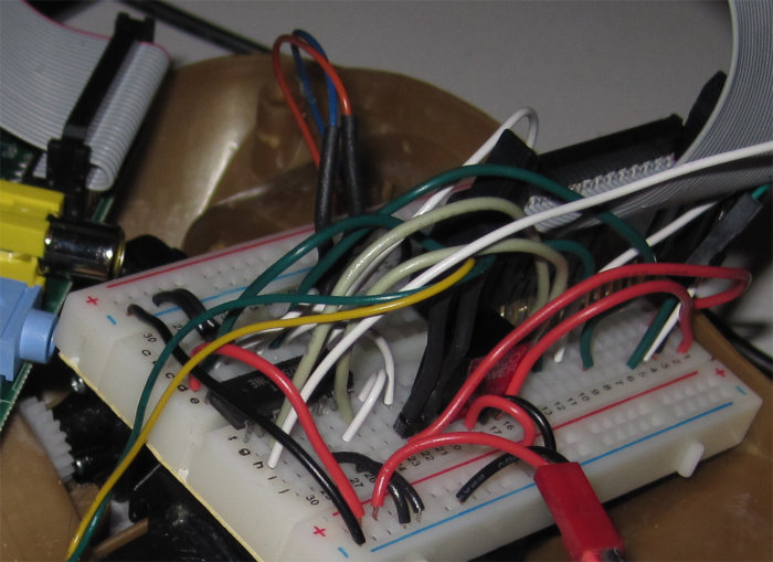