Shallow Thoughts : tags : arduino
Akkana's Musings on Open Source Computing and Technology, Science, and Nature.
Sat, 10 Mar 2018
![[Intel Galileo Gen2 by Mwilde2 on Wikimedia commons]](https://upload.wikimedia.org/wikipedia/commons/thumb/f/f8/IntelGalileoGen2.png/320px-IntelGalileoGen2.png) Our makerspace got a donation of a bunch of Galileo gen2 boards from Intel
(image
from Mwilde2
on Wikimedia commons).
Our makerspace got a donation of a bunch of Galileo gen2 boards from Intel
(image
from Mwilde2
on Wikimedia commons).
The Galileo line has been discontinued, so there's no support and
no community, but in theory they're fairly interesting boards.
You can use a Galileo in two ways: you can treat it
like an Arduino, after using the Arduino IDE to download a
Galileo hardware definition since they're not Atmega chips. They
even have Arduino-format headers so you can plug in an Arduino shield.
That works okay (once you figure out that you need to download
the Galileo v2 hardware definitions, not the regular Galileo).
But they run Linux under the hood, so you can also use them as a
single-board Linux computer.
Serial Cable
The first question is how to talk to the board. The documentation is terrible,
and web searches aren't much help because these boards were never
terribly popular. Worse, the v1 boards seem to have been more widely
adopted than the v2 boards, so a lot of what you find on the web
doesn't apply to v2. For instance, the v1 required a special serial cable
that used a headphone jack as its connector.
Some of the Intel documentation talks about how you can load a special
Arduino sketch that then disables the Arduino bootloader and instead
lets you use the USB cable as a serial monitor. That made me nervous:
once you load that sketch, Arduino mode no longer works until you
run a command on Linux to start it up again. So if the sketch doesn't
work, you may have no way to talk to the Galileo.
Given the state of the documentation I'd already struggled with for
Arduino mode, it didn't sound like a good gamble. I thought a real
serial cable sounded like a better option.
Of course, the Galileo documentation doesn't tell you what needs to
plug in where for a serial cable. The board does have a standard FTDI
6-pin header on the board next to the ethernet jack, and the labels on
the pins seemed to correspond to the standard pinout on my Adafruit
FTDI Friend: Gnd, CTS, VCC, TX, RX, RTS. So I tried that first, using
GNU screen to connect to it from Linux just like I would a Raspberry
Pi with a serial cable:
screen /dev/ttyUSB0 115200
Powered up the Galileo and sure enough, I got boot messages and was
able to log in as root with no password. It annoyingly forces orange
text on a black background, making it especially hard to read on
a light-background terminal, but hey, it's a start.
Later I tried a Raspberry Pi serial cable, with just RX (green), TX (white)
and Gnd (black) -- don't use the red VCC wire since the Galileo is already
getting power from its own power brick -- and that worked too. The Galileo
doesn't actually need CTS or RTS. So that's good: two easy ways to talk to
the board without buying specialized hardware. Funny they didn't bother
to mention it in the docs.
Blinking an LED from the Command Line
Once connected, how do you do anything? Most of the
Intel
tutorials on Linux are useless, devoting most of their space
to things like how to run Putty on Windows and no space at all to
how to talk to pins. But I finally found a
discussion thread
with a Python example for Galileo. That's not immediately helpful
since the built-in Linux doesn't have python installed (nor gcc,
natch). Fortunately, the Python example used files in /sys
rather than a dedicated Python library;
we can access /sys files just as well from the shell.
Of course, the first task is to blink an LED on pin 13. That
apparently corresponds to GPIO 7 (what are the other arduino/GPIO
correspondences? I haven't found a reference for that yet.) So you
need to export that pin (which creates /sys/class/gpio/gpio7
and set its direction to out. But that's not enough: the
pin still doesn't turn on when you
echo 1 > /sys/class/gpio/gpio7/value. Why not?
I don't know, but the Python script exports three other pins --
46, 30, and 31 -- and echoes 0 to 30 and 31. (It does this without
first setting their directions to out, and if you try
that, you'll get an error, so I'm not convinced the Python script
presented as the "Correct answer" would actually have worked. Be warned.)
Anyway, I ended up with these shell lines as
preparation before the Galileo can actually blink:
# echo 7 >/sys/class/gpio/export

# echo out > /sys/class/gpio/gpio7/direction

# echo 46 >/sys/class/gpio/export
# echo 30 >/sys/class/gpio/export
# echo 31 >/sys/class/gpio/export

# echo out > /sys/class/gpio/gpio30/direction
# echo out > /sys/class/gpio/gpio31/direction
# echo 0  > /sys/class/gpio/gpio30/value
# echo 0  > /sys/class/gpio/gpio31/value
And now, finally, you can control the LED on pin 13 (GPIO 7):
# echo 1 > /sys/class/gpio/gpio7/value
# echo 0 > /sys/class/gpio/gpio7/value
or run a blink loop:
# while /bin/true; do
> echo 1  > /sys/class/gpio/gpio7/value
> sleep 1
> echo 0  > /sys/class/gpio/gpio7/value
> sleep 1
> done
Searching Fruitlessly for a "Real" Linux Image
All the Galileo documentation is emphatic that you should download
a Linux distro and burn it to an SD card rather than using the Yocto
that comes preinstalled. The preinstalled Linux apparently has no
persistent storage, so not only does it not save your Linux programs,
it doesn't even remember the current Arduino sketch.
And it has no programming languages and only a rudimentary busybox shell.
So finding and downloading a Linux distro was the next step.
Unfortunately, that mostly led to dead ends. All the official Intel
docs describe different download filenames, and they all point to
generic download pages that no longer include any of the filenames
mentioned. Apparently Intel changed the name for its Galileo images
frequently and never updated its documentation.
After forty-five minutes of searching and clicking around,
I eventually found my way to
Intel® IoT Developer Kit Installer Files,
which includes sizable downloads with names like
- iss-iot-linux_12-09-16.tar.bz2 (324.07 MB),
- intel-iot-yocto.tar.xz (147.53 MB),
- intel-iot-wrs-pulsar-64.tar.xz (283.86 MB),
- intel-iot-wrs-32.tar.xz (386.16 MB), and
- intel-iot-ubuntu.tar.xz (209.44 MB)
From the size, I suspect those are all Linux images. But what are they
and how do they differ? Do any of them still have working repositories?
Which ones come with Python, with gcc, with GPIO support,
with useful development libraries? Do any of them get security updates?
As far as I can tell, the only way to tell is to download each image,
burn it to a card, boot from it, then explore the filesystem
trying to figure out what distro it is and how to try updating it.
But by this time I'd wasted three hours and gotten no
further than the shell commands to blink a single LED, and I ran out of
enthusiasm. I mean, I could spend five more hours on this, try several
of the Linux images, and see which one works best. Or I could spend
$10 on a Raspberry Pi Zero W that has abundant documentation,
libraries, books, and community howtos. Plus wi-fi, bluetooth and HDMI,
none of which the Galileo has.
Arduino and Linux Living Together
So that's as far as I've gone. But I do want to note
one useful thing I stumbled upon while searching
for information about Linux distributions:
Starting Arduino
sketch from Linux terminal shows how to run an Arduino sketch
(assuming it's already compiled) from Linux:
sketch.elf /dev/ttyGS0 &
It's a fairly cool option to have. Maybe one of these days, I'll pick
one of the many available distros and try it.
Tags: hardware, linux, intel, galileo, arduino
[
13:54 Mar 10, 2018
More hardware |
permalink to this entry |
]
Sat, 16 Dec 2017
Playing with the
ATtiny85
I was struck by how simple the circuit was.
Sure, I'd made a
homemade
Arduino on a breadboard;
but with the crystal and all the extra capacitors and resistors it ends
up seeming like a lot of parts and wires.
If an ATtiny can use a built-in clock and not need all those extra
parts, couldn't I use an Atmega328 the same way?
![[Circuit for Atmega328 on breadboard with ISP]](http://shallowsky.com/blog/images/arduino/bare-atmega-breadboard-isp_bb.jpg) Why, yes, as it turns out. But there are a few tricks.
Why, yes, as it turns out. But there are a few tricks.
Wire it
Wiring a bare Atmega chip is easy.
You'll want to keep a good pinout diagram handy, like this
Arduino
ATmega328 Pinout from HobbyTronics.
For the initial wiring, all you need is
two power and two ground lines, the pins marked - and +,
plus a pullup resistor on RST (something large, like 10kΩ).
The excellent tutorial
From
Arduino to a Microcontroller on a Breadboard is a good guide
if you need additional details: the third section
shows a circuit without external clock.
Add an LED and resistor on pin 13 (atmega pin 19, called SCK) so
you can test it using a blink program.
Now you need to set up the software.
Set up a hardware profile for a bare Arduino
To program it with the Arduino libraries,
you'll need a hardware definition for an atmega328 chip
with an internal clock. I used the download
from the last section of the excellent tutorial,
From
Arduino to a Microcontroller on a Breadboard. (Keep that page
up: it has good wiring diagrams.)
For Arduino 1.8.5, download breadboard-1-6-x.zip and unpack it
in your ~/sketchbook/hardware/ directory, making a directory
there called breadboard. Then you'll need to make one change:
the 1.6 directory is missing a file called pins_arduino.h",
so if you try to compile with this hardware definition, you'll get
an error like:
mkdir -p build-atmega328bb-atmega328
/usr/local/share/arduino/hardware/tools/avr/bin/avr-g++ -x c++ -include Arduino.h -MMD -c -mmcu=atmega328p -DF_CPU=8000000L -DARDUINO=185 -DARDUINO_ARCH_AVR -D__PROG_TYPES_COMPAT__ -I/usr/local/share/arduino/hardware/arduino/avr/cores/arduino -I/home/akkana/sketchbook/hardware/breadboard/avr/variants/standard    -Wall -ffunction-sections -fdata-sections -Os -fpermissive -fno-exceptions -std=gnu++11 -fno-threadsafe-statics -flto blink.ino -o build-atmega328bb-atmega328/blink.ino.o
In file included from :0:0:
/usr/local/share/arduino/hardware/arduino/avr/cores/arduino/Arduino.h:257:26: fatal error: pins_arduino.h: No such file or directory
 #include "pins_arduino.h"
                          ^
compilation terminated.
/usr/share/arduino/Arduino.mk:1251: recipe for target 'build-atmega328bb-atmega328/blink.ino.o' failed
make: *** [build-atmega328bb-atmega328/blink.ino.o] Error 1
The problem is that it's including these directories:
-I/usr/local/share/arduino/hardware/arduino/avr/cores/arduino
 -I/home/akkana/sketchbook/hardware/breadboard/avr/variants/standard
but the actual file is in:
/usr/local/share/arduino/hardware/arduino/avr/variants/standard/pins_arduino.h
You can fix that by making a link from the "standard" directory in your
Arduino install to breadboard/avr/variants/standard. On Linux, that would
be something like this (Mac and Windows people can substitute their
local equivalents):
ln -s /usr/local/share/arduino/hardware/arduino/avr/variants/standard ~/sketchbook/hardware/breadboard/avr/variants/
Now your hardware definition should be ready to go. To check, fire up
the IDE and look in Tools->Board for
ATmega328 on a breadboard (8 MHz internal clock).
Or if you use Arduino-mk, run
ALTERNATE_CORE=breadboard make show_boards
and make sure it lists
atmega328bb ATmega328 on a breadboard (8 MHz internal clock).
Reprogram the Fuses and Bootloader for an Internal Clock
The next trick is that an Atmega chip programmed with the Arduino
bootloader is also fused to use an external, 16MHz clock.
If you wire it to use its internal 8MHz clock, you won't be
able to talk to it with either an ISP or FTDI.
You'll definitely run into this if you pull the CPU out of an Arduino.
But even if you buy new chips you may see it:
many Atmega328s come pre-programmed with the Arduino bootloader.
After all, that's what most people want.
The easiest way to reprogram the fuses is to use the hardware
definition you just installed to burn a new bootloader, which resets
the fuse settings at the same time. So you need an In-System
Programmer, or ISP. You can use an Arduino as an ISP, but I'm told
that this tends to be flaky and isn't recommended. After I had
problems using an Arduino I ordered a cheap USBtinyUSP, which works
fine.
Regardless of which ISP you use, if you wire up your atmega without
an external clock when it's fused for one, you won't be able to burn a
bootloader. A typical error:
[ ... ]
Reading | ################################################## | 100% 0.02s

avrdude: Device signature = 0x000000 (retrying)

Error while burning bootloader.
Reading | ################################################## | 100% 0.02s

avrdude: Device signature = 0x000000
avrdude: Yikes!  Invalid device signature.
     Double check connections and try again, or use -F to override
     this check.
The solution is to burn the bootloader using an external clock.
You can add a crystal and two capacitors to your breadboard circuit
if you have them.
If not, an easy solution is to pull the chip out of the breadboard,
plug it into the socket in an Arduino and burn it there.
(Note: if you're using an Arduino as your ISP, you'll need a second
Arduino.)
Plug your ISP into the Arduino's ISP header: on an Uno, that's the
header labeled ICSP at the end of the chip farthest away from the USB
plug. It's a six-pin connector (2x3), it's easy to plug in backward
and you can't depend on either the Arduino's header or the ISP's cable
being labeled as to direction; if in doubt, use a multimeter in
continuity mode to see which pin is ground on each side, then make
sure those pins match. Once you're sure, mark your connector somehow
so you'll know next time.
In the Arduino IDE, set Tools->Board to
ATmega328 on a breadboard (8 MHz internal clock),
set Programmer to whatever ISP you're using.
then run Tools->Burn Bootloader.
If you're using Arduino-mk instead of the IDE,
set up a Makefile that looks like this:
ALTERNATE_CORE = breadboard
BOARD_TAG      = atmega328bb
ISP_PROG     = usbtiny
include /usr/local/share/Arduino-Makefile/Arduino.mk
Substitute your ISP, if different, and your location for Arduino.mk.
Then type
make burn_bootloader
Program it
Once you're wired, you should be able to program it either with an
FTDI board or an ISP, as I discussed in
homemade
Arduino, Part 1.
You should be able to use your minimal Atmega328 to
run anything you can run on a normal Arduino (albeit at half the
clock speed).
I plan to make a little board with a ZIF socket and connectors for
both the USBtinyISP and the FTDI Friend so I don't have to plug in
all those wires again each time.
Tags: hardware, arduino
[
13:14 Dec 16, 2017
More hardware |
permalink to this entry |
]
Sat, 09 Dec 2017
There are lots of tutorials around for building an Arduino on a
breadboard, using an Atmega328 (or the older 168) chip, a crystal,
a few capacitors and resistors and a power supply.
It's a fun project that every Arduino hacker should try at least once.
But while there are lots of instructions on how to wire up a breadboard
Arduino, most instructions on how to program one are confusing and incomplete.
Of course, you can program your Atmega chip while it's in an Arduino,
then unplug it from the Arduino's socket and move it to the
breadboard. But what a hassle! It's so more convenient to leave the chip
in the breadboard while you test new versions of the code. And you can,
in two different ways: with FTDI, which uses the Arduino bootloader,
or with an ISP, which doesn't.
Either way, start by downloading a good pinout diagram for the
Atmega328 chip. I use this one: the
Arduino
ATmega328 Pinout from HobbyTronics, which is very compact yet does a
good job of including both the mappings to Arduino digital and analog
pins and the functions like RX, TX, MOSI and MISO you'll need for
programming the chip.
Load Programs with FTDI
![[Circuit for Atmega328 on breadboard with FTDI friend]](http://shallowsky.com/blog/images/arduino/bare-atmega-breadboard-ftdi_bb.jpg) An FTDI board is a little trickier to wire than an ISP, but it's
less risky because it loads the code the same way an Arduino would,
so you don't overwrite the bootloader and you
can still put your chip back into an Arduino if things go wrong.
So let's start with FTDI.
An FTDI board is a little trickier to wire than an ISP, but it's
less risky because it loads the code the same way an Arduino would,
so you don't overwrite the bootloader and you
can still put your chip back into an Arduino if things go wrong.
So let's start with FTDI.
I use an
Adafruit "FTDI Friend", but there are lots of similar
FTDI boards from Sparkfun
and other vendors. They have six outputs,
but you'll need only five of those. Referring to your Atmega pinout,
wire up power, ground, TX, and RX. For some FTDI boards you may need
pullup resistors on the TX and RX lines; I didn't need them.
Now you have four pins connected.
Wiring the reset line is more complicated because it requires a
0.1μF capacitor. A lot of tutorials don't mention the capacitor,
but it didn't work for me without one.
Connect from RTS on the FTDI board, through the
0.1μF cap, to the RST line.
A 0.1μF capacitor is an electrolytic cap with a positive and a
negative lead, but the few online tutorials that even mention the
capacitor don't bother to say which side is whick. I connected the
FTDI friend to the cap's negative lead, and the positive lead to the
Atmega chip, and it worked.
You may also need a pullup on that RST/RTS line: a resistor
around 10kΩ from the RST pin 1 of the atmega chip to the 5v power line.
Note: the Fritzing diagram here shows pullup resistors on RST, TX
and RX. You may not need any of them.
Incidentally, RST stands for "reset", while RTS stands for "Ready To
Send"; they're not meant as anagrams of each other. The remaining pin
on the FTDI friend, CTS, is "Clear To Send" and isn't needed for an
Arduino.
Once the wiring is ready, plug in the FTDI board, check to make sure
Port is set to whatever port the FTDI board registered,
and try uploading a program as if you were uploading to a normal Arduino Uno.
And cross your fingers. If it doesn't work, try fiddling with pullups
and capacitor values.
Load Programs with an ISP
An In-System Programmer, or ISP, writes programs straight to the chip,
bypassing (and overwriting) the Arduino bootloader. You can also use
an ISP to burn a new bootloader and reprogram the fuses on your
Arduino, to change parameters like the clock rate. (More on that in Part 2.)
You can use an
Arduino as an ISP, but it's somewhat unreliable and
prone to unexplained errors. A dedicated ISP isn't expensive, is
easier to wire and is more likely to work. A common type of ISP is
called a "USBtinyISP", and you can buy one from vendors like
Sparkfun or
Adafruit,
or search for usbtinyisp on sites like ebay or aliexpress.
Update: I've been curious about this flakiness: why does "Arduino as ISP"
work fine for some people and utterly fail for others? One person I asked
thought it had to do with the way Arduinos reset the RESET line whenever
the serial port is opened: so RESET gets toggled at the wrong time as
the bootloader code is being transferred.
An alternate method that may get around this is
Gammon Forum's
Atmega bootloader programmer, which includes the bootloader bits
as part of the code so it doesn't need to re-open the serial port.
Someone else says a 10 uF capacitor between reset and ground should
prevent that from happening; and another person says it should be a
100nF capacitor between RST on the programmer and RST on the AVR-chip
plus a 10k pullup resistor,
Most Arduino-as-ISP tutorials, including the official ones on arduino.cc,
don't mention either capacitors or pullups,
so that may explain why the method works for some people and not others.
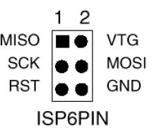 ISPs typically use a six-pin connector (2x3). It's not always easy to
figure out which end is which, so use a multimeter in continuity mode
to figure out which pin is ground. Once you're sure, mark your connector
so you'll know which pin is pin 1 (MISO, the pin opposite ground).
ISPs typically use a six-pin connector (2x3). It's not always easy to
figure out which end is which, so use a multimeter in continuity mode
to figure out which pin is ground. Once you're sure, mark your connector
so you'll know which pin is pin 1 (MISO, the pin opposite ground).
Once you have your ISP pins straight, refer to your handy-dandy
Atmega328 pinout and connect power, ground, MOSI, MISO, SCK, and RST
to the appropriate Atmega pins.
All wired up? In the Arduino IDE, set Programmer to your ISP,
for instance, USBtinyISP or Arduino as ISP
Then use the Upload button to upload sketches.
If you prefer Arduino-mk instead of the IDE, add this to your Makefile:
ISP_PROG = usbtiny
(or whatever ISP you're using). Then type
make ispload
instead of
make upload
Once you have your FTDI or ISP working, then you can think about making
an even simpler circuit -- without the external clock and its associated
capacitors. But there are a couple of additional tricks to that.
Stay tuned for Part 2.
Tags: hardware, arduino
[
15:44 Dec 09, 2017
More hardware |
permalink to this entry |
]
Wed, 29 Nov 2017
Having written a basic blink program in C for
my
ATtiny85 with a USBtinyISP (Part 1), I wanted to use it to control other
types of hardware. That meant I wanted to be able to use Arduino libraries.
The Arduino IDE
I normally use Makefiles, but the Arduino IDE is much better supported
so I tried that first. I followed the steps at
High-Low
Tech: Programming an ATtiny w/ Arduino 1.6 (or 1.0).
But the short summary is:
- Run the Arduino IDE
- File->Preferences
- In "Additional Boards Manager" near the bottom, paste this:
https://raw.githubusercontent.com/damellis/attiny/ide-1.6.x-boards-manager/package_damellis_attiny_index.json
and click OK
- Tools->Boards->Board Manager...
- Find the ATTiny entry, click on it, and click Install
- Back in the main Arduino IDE, Tools->Boards should now havea
couple of Attiny entries. Choose the one that corresponds to your
ATTiny; then, under Processor, narrow it down further.
In
Tools->Programmer, choose the programmer you're using
(for example,
USBtinyISP).
Now you should be able to Verify and Upload a blink sketch
just like you would to a regular Arduino, subject to the pin limitations
of the ATTiny.
That worked for blink. But it didn't work when I started adding libraries.
Since the command-line was what I really cared about, I moved on rather
than worrying about libraries just yet.
ATtiny with Arduino-Makefile
For most of my Arduino development I use an excellent package called
Arduino-Makefile.
There's a Debian package called arduino-mk that works fine for normal
Arduinos, but for ATtiny, there have been changes, so use the version
from git.
A minimal blink Makefile looks like this:
BOARD_TAG = uno
include /usr/share/arduino/Arduino.mk
It assumes that if you're in a directory called blink, it
should compile a file called blink.ino. It will also build
any additional .cpp files it finds there. make upload
uploads the code to a normal Arduino.
With Attiny it gets quite a bit more complicated.
The key is that you have to specify an alternate core:
ALTERNATE_CORE = ATTinyCore
But there are lots of different ATtiny cores, they're all different,
and they each need a different set of specifiers like BOARD_TAG in
the Makefile. Arduino-Makefile comes with an example, but it isn't
very useful since it doesn't say where to get the cores that correspond
with the various samples. I ended up filing a documentation bug and
exchanging some back-and-forth with the maintainer of the package,
Simon John, and here's what I learned.
First: as I mentioned earlier, you should use the latest git version
of Arduino-Makefile. The version in Debian is a little older and some
things have changed; while the older version can be made to work with
ATtiny, the recipes will be different from the ones here.
Second, the recipes for each core will be different depending on which
version of the Arduino software you're using. Simon
says he sticks to version 1.0.5 when he uses ATtinys, because newer
versions don't work as well. That may be smart (certainly he has a lot
more experience than I do), but I'm always hesitant to rely on
software that old, so I wanted to get things working with the latest
Arduino, 1.8.5, if i could, so that's what the recipes here will
reflect.
Third, as mentioned in Part 1, clock rate should be 1MHz, not 8MHz
as you'll see in a lot of web examples, so:
F_CPU = 1000000L
Fourth, uploading sketches. As mentioned in the last article, I'm using
a USBtinyISP. For that, I use ISP_PROG = usbtiny and
sketches are uploaded by typing make ispload rather than
the usual make upload. change that if you're usinga
different programmer.
With those preliminaries over:
I ended up getting two different cores working,
and there were two that didn't work.
Install the cores in subdirectories in
your ~/sketchbook/hardware directory. You can have multiple
cores installed at once if you want to test different cores.
Here are the recipes.
CodingBadly's arduino-tiny
This is the core that Simon says he prefers, so it's the one I'm going
to use as my default. It's at
https://github.com/Coding-Badly/arduino-tiny.git,
and also a version on Google Code. (Neither one has been updated since 2013.)
git clone it into your sketchbook/hardware.
Then either cp 'Prospective Boards.txt' boards.txt
or create a new boards.txt and copy from 'Prospective Boards.txt'
all the boards you're interested in (for instance, all the attiny85
definitions if attiny85 is the only attiny board you have).
Then your Makefile should look something like this:
ARDUINO_DIR = /path/to/arduino-1.8.5

BOARD_TAG = attiny85at8
ALTERNATE_CORE = tiny
F_CPU = 1000000L
ISP_PROG = usbtiny

include /path/to/Arduino-Makefile/Arduino.mk
If your Arduino software is installed in /usr/share/arduino you can
omit the first line.
Now copy blink.ino -- of course, you'll have to change pin 13
to be something between 1 and 6 since that's how many pins an ATtiny
has -- and try make and make ispload.
SpenceKonde's ATTinyCore
This core is at https://github.com/SpenceKonde/ATTinyCore.git.
I didn't need to copy boards.txt or make any other changes,
just clone it under sketches/hardware and then use this Makefile:
ARDUINO_DIR = /path/to/arduino-1.8.5

ALTERNATE_CORE = ATTinyCore
BOARD_TAG = attinyx5
BOARD_SUB = 85
F_CPU = 1000000L
ISP_PROG = usbtiny

include /path/to/Arduino-Makefile/Arduino.mk
Non-working Cores
There are plenty of other ATtiny cores around. Here are two that
apparently worked once, but I couldn't get them working with the
current version of the tools. I'll omit links to them to try to
reduce the probability of search engines linking to them rather
than to the more up-to-date cores.
Damellis's attiny (you may see this referred to as HLT after the
domain name, "Highlowtech"), on GitHub as
damellis/attiny,
was the first core I got working with Debian's older version of
arduino-mk and Arduino 1.8.4. But when I upgraded to the latest
Arduino-Makefile and Arduino 1.8.5, it no longer worked. Ironic since
an older version of it was the one used in most of the tutorials I
found for using ATtiny with the Arduino IDE.
Simon says this core is buggy: in particular, there are problems with
software PWM.
I also tried rexxar-tc's arduino-tiny.core2 (also on GitHub).
I couldn't get it to work with any of the Makefile or Arduino
versions I tried, though it may have worked with Arduino 1.0.
With two working cores, I can get an LED to blink.
But libraries are the point of using the Arduino framework ...
and as I tried to move beyond blink.ino, I found that
not all Arduino libraries work with ATtiny.
In particular, Wire, used for protocols like I2C to talk to all
kinds of useful chips, doesn't work without substantial revisions.
But that's a whole separate topic. Stay tuned.
Tags: hardware, arduino, programming
[
19:06 Nov 29, 2017
More hardware |
permalink to this entry |
]
Thu, 02 Nov 2017
![[ATtiny85 and USBtinyISP programmer]](http://shallowsky.com/blog/images/hardware/img_1889sm.jpg) Arduinos are great for prototyping, but for a small, low-power,
cheap and simple design, an ATtiny chip seems like just the ticket.
For just a few dollars you can do most of what you could with an
Arduino and use a lot of the same code, as long as you can make do
with a little less memory and fewer pins.
Arduinos are great for prototyping, but for a small, low-power,
cheap and simple design, an ATtiny chip seems like just the ticket.
For just a few dollars you can do most of what you could with an
Arduino and use a lot of the same code, as long as you can make do
with a little less memory and fewer pins.
I've been wanting to try them, and recently I ordered a few ATtiny85 chips.
There are quite a few ways to program them. You can buy programmers
specifically intended for an ATtiny, but I already had a USBtinyISP,
a chip used to program Arduino bootloaders, so that's what I'll
discuss here.
Wiring to the USBtinyISP
![[ATtiny85 and USBtinyISP wiring]](http://shallowsky.com/blog/images/hardware/attiny-usbtinyISP_bb.jpg) The best reference I found on wiring was
Using USBTinyISP to program ATTiny45 and ATTiny85.
That's pretty clear, but I made my own Fritzing diagram, with colors,
so it'll be easy to reconstruct it next time I need it.
The colors I used:
The best reference I found on wiring was
Using USBTinyISP to program ATTiny45 and ATTiny85.
That's pretty clear, but I made my own Fritzing diagram, with colors,
so it'll be easy to reconstruct it next time I need it.
The colors I used:
| MISO
| yellow
| VCC | red
|
| SCK
| white
| MOSI | green
|
| RESET
| orange
or red/black
| GND | black
|
Programming the ATtiny in C
I found a couple of blink examples at
electronut.in,
Getting Started with ATtiny AVR programming,
and in a Stack Exchange thread,
How
to program an AVR chip in Linux
Here's some basic blink code:
#include <avr/io.h>
#include <util/delay.h>

int main (void)
{
    // Set Data Direction to output on port B, pins 2 and 3:
    DDRB = 0b00001000;
    while (1) {
        // set PB3 high
        PORTB = 0b00001000;
        _delay_ms(500);
        // set PB3 low
        PORTB = 0b00000000;
        _delay_ms(500);
    }

    return 1;
}
Then you need a Makefile. I started with the one linked from the electronut
page above. Modify it if you're using a programmer other than a USBtinyISP.
make builds the program, and make install
loads it to the ATtiny. And, incredibly, my light started blinking,
the first time!
![[ATtiny85 pinout]](http://shallowsky.com/blog/images/hardware/attiny85-pinout.jpg) Encouraged, I added another LED to make sure I understood.
The ATtiny85 has six pins you can use (the other two are power and ground).
The pin numbers correspond to the bits in DDRB and PORTB:
my LED was on PB3. I added another LED on PB2 and made it alternate
with the first one:
Encouraged, I added another LED to make sure I understood.
The ATtiny85 has six pins you can use (the other two are power and ground).
The pin numbers correspond to the bits in DDRB and PORTB:
my LED was on PB3. I added another LED on PB2 and made it alternate
with the first one:
    DDRB = 0b00001100;
[ ... ]
        // set PB3 high, PB2 low
        PORTB = 0b00001000;
        _delay_ms(500);
        // set PB3 low, PB2 high
        PORTB = 0b00000100;
        _delay_ms(500);
Timing Woes
But wait -- not everything was rosy. I was calling _delay_ms(500),
but it was waiting a lot longer than half a second between flashes.
What was wrong?
For some reason, a lot of ATtiny sample code on the web assumes the
chip is running at 8MHz. The chip's internal oscillator is indeed 8MHz
(though you can also run it with an external crystal at various
speeds) -- but its default mode uses that oscillator in "divide by
eight" mode, meaning its actual clock rate is 1MHz. But Makefiles
you'll find on the web don't take that into account (maybe because
they're all copied from the same original source). So, for instance,
the Makefile I got from electronut has
CLOCK = 8000000
If I changed that to
CLOCK = 1000000
now my delays were proper milliseconds, as I'd specified.
Here's my working
attiny85
blink Makefile.
In case you're curious about clock rate, it's specified by what are
called fuses, which sound permanent but aren't: they hold their
values when the chip loses power, but you can set them over and over.
You can read the current fuse settings like this:
avrdude -c usbtiny -p attiny85 -U lfuse:r:-:i -v
which should print something like this:
avrdude: safemode: hfuse reads as DF
avrdude: safemode: efuse reads as FF
avrdude: safemode: Fuses OK (E:FF, H:DF, L:62)
To figure out what that means, go to the
Fuse calculator,
scroll down to Current settings and enter the three values
you got from avrdude (E, H and L correspond to Extended, High and Low).
Then scroll up to Feature configuration
to see what the fuse settings correspond to.
In my case it was
Int. RC Osc. 8 Mhz; Start-up time PWRDWN/RESET; 6CK/14CK+
64ms; [CKSEL=1011 SUT=10]; default value
and Divide clock by 8 internally; [CKDIV8=0] was checked.
More on ports and pins
There's more info on ATtiny ports in
ATTiny
Port Manipulation (Part 1): PinMode() and DigitalWrite()
Nobody seems to have written much about AVR/ATTINY
programming in general. Symbols like PORTB and
functions like _delay_ms() come from files in
/usr/lib/avr/include/, at least on my Debian system.
There's not much there, so if you want library functions to handle
nontrivial hardware, you'll have to write them or find them somewhere else.
As for understanding pins, you're supposed to go to the datasheet and read it
through, all 234 pages. Hint: for understanding basics of reading from and
writing to ports, speed forward to section 10, I/O Ports.
A short excerpt from that section:
Three I/O memory address locations are allocated for each port, one
each for the Data Register - PORTx, Data Direction Register - DDRx,
and the Port Input Pins - PINx. The Port Input Pins I/O location is
read only, while the Data Register and the Data Direction Register are
read/write. However, writing a logic one to a bit in the PINx
Register, (comma sic) will result in a toggle in the
corresponding Data Register. In addition, the Pull-up Disable - PUD
bit in MCUCR disables the pull-up function for all pins in all ports
when set.
There's also some interesting information there about built-in pull-up
resistors and how to activate or deactivate them.
That's helpful, but here's the part I wish they'd said:
PORTB (along with DDRB and PINB) represents all six pins. (Why B? Is
there a PORTA? Not as far as I can tell; at least, no PORTA is
mentioned in the datasheet.) There are six output pins, corresponding
to the six pins on the chip that are not power or ground. Set the bits
in DDRB and PORTB to correspond to the pins you want to set. So if you
want to use pins 0 through 3 for output, do this:
DDRB = 0b00001111;
If you want to set logical pins 1 and 3 (corresponding to pins 6 and 2
on the chip) high, and the rest of the pins low, do this:
PORTB = 0b00001010;
To read from pins, use PINB.
In addition to basic functionality, all the pins have specialized
uses, like timers, SPI, ADC and even temperature measurement (see the
diagram above). The datasheet goes into more detail about how to get
into some of those specialized modes.
But a lot of those specialties are easier to deal with using
libraries. And there are a lot more libraries available for the Arduino
C++ environment than there are for a bare ATtiny using C.
So the next step is to program the ATtiny using Arduino ...
which deserves its own article.
Tags: hardware, arduino, programming
[
18:01 Nov 02, 2017
More hardware |
permalink to this entry |
]
Mon, 04 Sep 2017
![[Raspberry Pi Zero W]](http://shallowsky.com/blog/images/pi-no-headers.jpg) My new book is now shipping! And it's being launched via a terrific Humble
Bundle of books on electronics, making, Raspberry Pi and Arduino.
My new book is now shipping! And it's being launched via a terrific Humble
Bundle of books on electronics, making, Raspberry Pi and Arduino.
Humble Bundles, if you haven't encountered them before, let you pay
what you want for a bundle of books on related subjects. The books are
available in ePub, Mobi, and PDF formats, without DRM, so you can read
them on your choice of device. If you pay above a certain amount,
they add additional books. My book is available if you pay $15 or more.
You can also designate some of the money you pay for charity.
In this case the charity is Maker Ed,
a crowdfunding initiative that supports Maker programs primarily
targeted toward kids in schools. (I don't know any more about them
than that; check out their website for more information.)
Jumpstarting the Raspberry Pi Zero W is a short book,
with only 103 pages in four chapters:
- Getting Started: includes tips on headless setup and the Linux
command line;
- Blink an LED: includes ways to blink and fade LEDs from the shell
and from several different Python libraries;
- A Temperature Notifier and Fan Control: code and wiring
instructions for three different temperature sensors (plus humidity
and barometric pressure), and a way to use them to control your house
fan or air conditioner, either according to the temperature in the room
or through a Twitter command;
- A Wearable News Alert Light Show: wire up NeoPixels or DotStars
and make them respond to keywords on Twitter or on any other web page
you choose, plus some information on powering a Pi portably with batteries.
All the code and wiring diagrams from the book, plus a few extras, are
available on Github, at my
Raspberry Pi Zero
Book code repository.
To see the book bundle, go to the
Electronics
& Programming Humble Bundle and check out the selections.
My book, Jumpstarting the Raspberry Pi Zero W, is available if
you pay $15 or more -- along with tons of other books you'll probably
also want. I already have Make: Electronics and it's one of the
best introductory electronics books I've seen, so I'm looking forward
to seeing the followup volume. Plus there are books on atmospheric and
environmental monitoring, a three-volume electronic components
encyclopedia, books on wearable electronics and drones and other cool stuff.
I know this sounds like a commercial, but this bundle really does look
like a great deal, whether or not you specifically want my Pi book,
and it's a limited-time offer, only good for six more days.
Tags: writing, raspberry pi, electronics, maker, arduino
[
13:21 Sep 04, 2017
More writing |
permalink to this entry |
]
Wed, 16 Jul 2014
![[Arduino intervalometer]](http://shallowsky.com/blog/images/hardware/img_6213-450.jpg) While testing my
automated critter
camera, I was getting lots of false positives caused by clouds
gathering and growing and then evaporating away. False positives
are annoying, but I discovered that it's fun watching the clouds grow
and change in all those photos
... which got me thinking about time-lapse photography.
While testing my
automated critter
camera, I was getting lots of false positives caused by clouds
gathering and growing and then evaporating away. False positives
are annoying, but I discovered that it's fun watching the clouds grow
and change in all those photos
... which got me thinking about time-lapse photography.
First, a disclaimer: it's easy and cheap to just buy an
intervalometer. Search for timer remote control
or intervalometer and you'll find plenty of options for
around $20-30. In fact, I ordered one.
But, hey, it's not here yet, and I'm impatient.
And I've always wanted to try controlling a camera from an Arduino.
This seemed like the perfect excuse.
Why an Arduino rather than a Raspberry Pi or BeagleBone? Just because
it's simpler and cheaper, and this project doesn't need much compute
power. But everything here should be applicable to any microcontroller.
My Canon Rebel Xsi has a fairly simple wired remote control plug:
a standard 2.5mm stereo phone plug.
I say "standard" as though you can just walk into Radio Shack and buy
one, but in fact it turned out to be surprisingly difficult, even when
I was in Silicon Valley, to find them. Fortunately, I had found some,
several years ago, and had cables already wired up waiting for an experiment.
The outside connector ("sleeve") of the plug is ground.
Connecting ground to the middle ("ring") conductor makes the camera focus,
like pressing the shutter button halfway; connecting ground to the center
("tip") conductor makes it take a picture.
I have a wired cable release that I use for astronomy and spent a few
minutes with an ohmmeter verifying what did what, but if you don't
happen to have a cable release and a multimeter there are plenty of
Canon
remote control pinout diagrams on the web.
Now we need a way for the controller to connect one pin of the remote
to another on command.
There are ways to simulate that with transistors -- my
Arduino-controlled
robotic shark project did that. However, the shark was about a $40
toy, while my DSLR cost quite a bit more than that. While I
did find several people on the web saying they'd used transistors with
a DSLR with no ill effects, I found a lot more who were nervous about
trying it. I decided I was one of the nervous ones.
The alternative to transistors is to use something like a relay. In a relay,
voltage applied across one pair of contacts -- the signal from the
controller -- creates a magnetic field that closes a switch and joins
another pair of contacts -- the wires going to the camera's remote.
But there's a problem with relays: that magnetic field, when it
collapses, can send a pulse of current back up the wire to the controller,
possibly damaging it.
There's another alternative, though. An opto-isolator works like a
relay but without the magnetic pulse problem. Instead of a magnetic
field, it uses an LED (internally, inside the chip where you can't see it)
and a photo sensor. I bought some opto-isolators a while back and had
been looking for an excuse to try one. Actually two: I needed one for
the focus pin and one for the shutter pin.
How do you choose which opto-isolator to use out of the gazillion
options available in a components catalog? I don't know, but when I
bought a selection of them a few years ago, it included a 4N25, 4N26
and 4N27, which seem to be popular and well documented, as well as a
few other models that are so unpopular I couldn't even find a
datasheet for them. So I went with the 4N25.
Wiring an opto-isolator is easy. You do need a resistor across the inputs
(presumably because it's an LED).
380Ω
is apparently a good value for the 4N25, but
it's not critical. I didn't have any 380Ω but I had a bunch of
330Ω so that's what I used. The inputs (the signals from the Arduino)
go between pins 1 and 2, with a resistor; the outputs (the wires to the
camera remote plug) go between pins 4 and 5, as shown in
the diagram on this
Arduino
and Opto-isolators discussion, except that I didn't use any pull-up
resistor on the output.
Then you just need a simple Arduino program to drive the inputs.
Apparently the camera wants to see a focus half-press before it gets
the input to trigger the shutter, so I put in a slight delay there,
and another delay while I "hold the shutter button down" before
releasing both of them.
Here's some Arduino code to shoot a photo every ten seconds:
int focusPin = 6;
int shutterPin = 7;

int focusDelay = 50;
int shutterOpen = 100;
int betweenPictures = 10000;

void setup()
{
    pinMode(focusPin, OUTPUT);
    pinMode(shutterPin, OUTPUT);
}

void snapPhoto()
{
    digitalWrite(focusPin, HIGH);
    delay(focusDelay);
    digitalWrite(shutterPin, HIGH);
    delay(shutterOpen);
    digitalWrite(shutterPin, LOW);
    digitalWrite(focusPin, LOW);
}

void loop()
{
    delay(betweenPictures);
    snapPhoto();
}
Naturally, since then we haven't had any dramatic clouds, and the
lightning storms have all been late at night after I went to bed.
(I don't want to leave my nice camera out unattended in a rainstorm.)
But my intervalometer seemed to work fine in short tests.
Eventually I'll make some actual time-lapse movies ... but that will
be a separate article.
Tags: arduino, hardware, photography, intervalometer, time-lapse, maker
[
18:31 Jul 16, 2014
More hardware |
permalink to this entry |
]
Wed, 18 Sep 2013
I found myself wanting to upload a sketch to an Arduino Pro Mini
recently, using an FTDI
Friend, and found that how to do it was surprisingly undocumented.
![[Arduino Pro Mini]](http://shallowsky.com/blog/images/arduino/ArduinoProMini.jpg)
![[Arduino Pro Mini]](http://shallowsky.com/blog/images/arduino/ftdi-friend.jpg)
First, the important thing is that the six FTDI pins do match up with
the six pins at the edge of the Pro Mini, though obviously you have
to figure out which way to rotate the two boards so you won't be 180
degrees off. I wasn't clear on that since the labels on the pins
don't seem to match (see below).
Second, if you haven't soldered headers to your Pro Mini, you can
stick a female-female header into the FTDI Friend's female header.
then insert the other side of the header into the holes in the Pro
Mini at an angle -- hold them with some tension so that the header
pins are making contact with the copper-plated rims of the Pro Mini
holes.
Okay, so the big question is which way to match the pins.
It's complicated by the Pro Mini's having both outer holes unlabeled.
Usually when trying to match pins I start by looking for Ground,
and make sure the two Grounds match. That doesn't work here --
the FTDI has the Gnd on one of the outer pins, while the
Pro Mini has Gnd on the second pin in. The pin parked Gnd on the Pro
Mini goes to CTS on the FTDI, while the pin parked Gnd on the FTDI
corresponds to a pin on the Pro Mini that's unmarked.
If you turned one of them 180 degrees, then you'd have Gnd (Pro Mini)
- Rx (FTDI), and Gnd (FTDI) - unmarked (Pro Mini). No help there.
So ignore Ground and use VCC as your guide. It's on the third pin in --
so only in one orientation will VCC on both boards match. That's the
orientation you want, and it works.
On some Pro Minis and some FTDI boards, you'll also have a label for
"GREEN" or "GRN" on one side, and "BLACK" or "BLK" on the other.
Match those if you have them, but you may not find that on all boards,
particularly if you ever hook up to clone or third-party boards.
So stick to VCC as a guide and you should be okay.
So what are those outer two holes on the Pro Mini?
An image search for
Arduino Pro Mini Pinout gives some pages showing GRN as
TX and BLK as +9V (I assume that would be Vin, but actually those pages
seem to be referring to the Arduino Mini, not the Pro Mini).
But another shows GRN as RESET and BLK as Gnd.
The official
Pro Mini schematic shows the outer pins on JP1 as DTR and GND.
So that seems most likely.
Tags: arduino, hardware, maker
[
16:28 Sep 18, 2013
More hardware |
permalink to this entry |
]
Sat, 29 Jun 2013
![[GetSET Robots and Sensors workshop]](http://shallowsky.com/blog/images/getset2013/img_7756.jpg) Wednesday I taught my "Robotics and Sensors" workshop at
the SWE GetSET summer camp.
Wednesday I taught my "Robotics and Sensors" workshop at
the SWE GetSET summer camp.
It was lots of fun, and definitely better than last year. It helped that
I had a wonderful set of volunteers helping out -- five women from
CodeChix (besides myself), so we had
lots of programming expertise, plus a hardware engineer who was
wonderfully helpful with debugging circuits. Thanks so much to all the
volunteers! You really made the workshop!
We also had a great group of girls -- 14 high school seniors, all smart
and motivated, working in teams of two.
How much detail?
One big issue when designing a one-day programming workshop is how
much detail to provide in each example, and how much to leave to the
students to work out. Different people learn differently. I'm the sort
who learns from struggling through a problem, not from simply copying
an example, and last year I think I erred too much in that direction,
giving minimal information and encouraging the girls to work out the rest.
Some of them did fine, but others found it frustrating. In a one-day
workshop, if you have to spend too much time working everything out,
you might never get to the fun stuff.
So this year I took a different approach. For each new piece of hardware,
I gave them one small, but complete, working example, then suggested
ways they could develop that. So for the first example
(File->Examples->Basic->Blink is everyone's first
Arduino exercise), I gave everyone two LEDs and two resistors, and
as soon as they got their first LED blinking, I encouraged them to
try adding another.
It developed that about half the teams wired their second
LED right next to the first one, still on pin 13. Clever! but not what
I'd had in mind.
So I encouraged them to try moving the second LED to a different pin,
like pin 12, and see if they could make one LED turn on while the
other one turned off.
Another challenge with workshops is that people work at very different
speeds. You have to have projects the fast students can work on to keep them
from getting bored while the rest are catching up. So for LEDs, having
a box full of extra LEDs helped, and by the time we were ready to move on,
they had some great light shows going -- tri-colored blinkers, fast
flashers, slow double-blinks.
I had pushbuttons on the tentative agenda but I was pretty sure that
we'd skip that part. Pushbuttons are useful but they aren't really all
that much fun. You have to worry about details like pull-down resistors
and debouncing, too much detail when you have only six hours total.
Potentiometers are more rewarding. We went through
File->Examples->03.Analog->AnalogInput,
and a few teams also tried LED fading with
File->Examples->03.Analog->AnalogInOutSerial.
Music
![[GetSET Robots and Sensors workshop]](http://shallowsky.com/blog/images/getset2013/img_7761.jpg) But then we moved on to what was really the highlight of the day,
piezo speakers.
Again, I provided a small working
example
program to create a rising tone. The Arduino IDE has no good
speaker examples built in, so I'd made a short url for my
Robots and Sensors
workshop page,
But then we moved on to what was really the highlight of the day,
piezo speakers.
Again, I provided a small working
example
program to create a rising tone. The Arduino IDE has no good
speaker examples built in, so I'd made a short url for my
Robots and Sensors
workshop page, is.gd/getset, to make it easyto
copy/paste code. It took no time at all before their speakers were
making noise.
I was afraid they'd just stop there ...
but as it turned out, everybody was energized
(including me and the other volunteers) by all the funny noises,
and without any prompting the girls immediately got to work changing
their tones, making them rise faster or slower, or (with some help
from volunteers) making them fall instead of rise. Every team had
different sounds, and everybody was laughing and having fun as they
tweaked their code.
In fact, that happened so fast that we ended up with plenty of time
left before lunch. My plan was to do speakers right before lunch because
noise is distracting, and after you've done that you can't to
concentrate on anything else for a while. So I let them continue to
play with the speakers.
I was glad I did. At least three different teams took the initiative
to search the web and find sample code for playing music.
There were some hitches -- a lot of the code samples needed to be
tweaked a bit, from changing the pin where the speaker was plugged in,
to downloading an include file of musical notes. One page gave code
that didn't compile at all. But it was exciting to watch -- after all,
this sort of experimentation and trial-and-error is a big part
of what programmers do, and they all eventually got their music projects
working.
One thing I learned was that providing a complete working
.ino file makes a big difference. Some of the "music on Arduino"
pages the girls found provided C functions but no hints as to how
to call those functions. (It wasn't obvious to me, either.)
Some of my own examples for the afternoon projects were like that,
providing code snippets without setup() and loop(), and some teams
were at sea, unsure how to create setup() and loop(). Of course
I'd explained about setup() and loop() during the initial blink
exercise. But considering how much material we covered in such a short
time, it's not reasonable to expect everybody to remember details like
that. And the Arduino IDE error messages aren't terribly easy to read,
especially showing up orange on black in a tiny 3-line space at the
bottom of the window.
So, for future workshops, I'll provide complete .ino files for all my
own examples, plus a skeleton file with an empty setup() and loop()
already there.
It's okay to spoon feed basic details like the structure of an .ino
file if it gives the students more time to think about the really
interesting parts of their project.
Afternoon projects
![[Working on the robotic car]](http://shallowsky.com/blog/images/getset2013/img_7766.jpg) After lunch, the afternoon was devoted to projects. Teams could pick
anything we had hardware for, work on it throughout the afternoon and
present it at the end of the workshop. There were two teams working on
robotic cars (sadly, as with so many motor projects, the hardware
ended up being too flaky and the cars didn't do much).
Other teams worked with sonar rangefinders, light sensors or tilt
switches, while some continued to work on their lights and music.
After lunch, the afternoon was devoted to projects. Teams could pick
anything we had hardware for, work on it throughout the afternoon and
present it at the end of the workshop. There were two teams working on
robotic cars (sadly, as with so many motor projects, the hardware
ended up being too flaky and the cars didn't do much).
Other teams worked with sonar rangefinders, light sensors or tilt
switches, while some continued to work on their lights and music.
Everybody seemed like they were having a good time, and I'd seen a lot of
working (or at least partly working) projects as I walked around
during the afternoon, but when it came to present what they'd done,
I was a little sad.
There was a lot of "Well, I tried this, but I couldn't get it to work,
so then I switched to doing this." Of course, trying things and
changing course are also part of engineering ... that sentence
describes a lot of my own playing with hardware, now that I think of
it. But still ... I was sad hearing it.
Notes for next time
So, overall, I was happy with the workshop. I haven't seen the evaluation
forms yet, but it sure seemed like everybody was having fun,
and I know we volunteers did.
What are the points I want to remember for next time?
- Start with small but complete working examples to introduce each
new hardware component.
- Provide complete .ino files, not just code snippets.
- Skip pushbuttons, but do try to cover AnalogInOutSerial and PWM output.
Or at least have printed handouts explaining the PWM outputs and LED fading.
- Turnkey kits are good: the less "connect the blue wire to pin 7,
the green one to pin 8" the better. For things like cars, I'd
like something already wired up with battery and shield,
"Just add Arduino".
- Keep a closer eye on the afternoon projects -- try to make sure
each team has something they're proud to show off.
Thanks again to the great volunteers! I'm looking forward to giving
this workshop again.
Tags: robots, arduino, education, hardware, programming, maker
[
20:36 Jun 29, 2013
More education |
permalink to this entry |
]
Sun, 23 Jun 2013
![[Servo wired up to Arduino, without separate battery]](http://shallowsky.com/arduino/class/servo-wired.jpg) My quest to make physical things move with Arduinos continues as we
ramp up to Wednesday's GetSET workshop.
My quest to make physical things move with Arduinos continues as we
ramp up to Wednesday's GetSET workshop.
A few nights ago I finally broke out some old airplane servos and
hooked them up to the Arduino. Don't know why I'd never gotten around
to that, but I hadn't.
I had to decode the wire colors, aided by this excellent
Connector
Types page from Servo City. The GWS Naro servo I chose, with a
JR plug, has a red wire (power), a brown wire (ground) and an orange
wire (signal). Easy enough.
The Arduino software has a built-in
Servo library,
with instructions on wiring things up and a sample "Sweep" program
to run the servo through its paces. Easy. I hooked it up and in just a
few minutes I had the servo arm sweeping. Servos are so easy!
Or so I thought.
The next day, I tried turning it into a real application, and
that's where my problems started. I added a couple of photoresistors
to my basic servo circuit and wrote a quick sketch to hook up the servo
and print the output from the photoresistors to the serial port,
as a first step before making it actually move the servos in response
to the light coming in.
And ... nothing. Not only did I not get any output on my serial
console, but I couldn't even open the serial console -- /dev/ttyACM0
didn't exist on my computer, or if it did, I got an error trying to
open it. I couldn't even download new versions of the sketch,
since those, too, are downloaded over the ACM0 serial device.
It turns out that servos, like larger motors, need a separate power
source. Sometimes you can get away with powering them from the
Arduino's 5v supply, but sometimes it will lead to flaky results.
This is contrary to every tutorial I found on the web.
The official Arduino.cc
Servo library documentation says
"The power wire is typically red, and should be connected to the 5V
pin on the Arduino board."
and adds
"Note that servos draw considerable power, so if you need to drive
more than one or two, you'll probably need to power them from a
separate supply (i.e. not the +5V pin on your Arduino). Be sure to
connect the grounds of the Arduino and external power supply together."
And the Adafruit motor
shield documentation says,
"Servos are powered off of the same regulated 5V that the Arduino
uses. This is OK for the small hobby servos suggested. If you want
something beefier, cut the trace going to + on the servo connectors
and wire up your own 5-6V supply!"
Basically, everywhere you turn people will tell you that for one or two
servos, there's no point in fussing with a separate power supply.
But when I went to the #arduino IRC channel, the experts there assured
me that all the web tutorials were wrong, and that power was almost
certainly my problem -- even with a single tiny GWS Naro servo.
And sure enough, when I added a 7.4v li-po battery as the power source
for the servo, all my problems went away. Serial communication worked
fine, and the servo was less jumpy. It's probably less risky to the
Arduino, too.
The weirdest part of all this? When I tried to power it all off the
Arduino's power supply (from USB), the servo was working fine, moving
to wherever I told it. It was just serial communications to the PC
that was failing.
I still have yet to find a good, simple way to power servos
if you can't power them off the Arduino's 5v supply.
Apparently their maximum voltage is 6V, and it's risky giving them
any more than that.
Right now I have a 7.4V li-po pack going through a speed controller;
I'm not using the speed controller for anything except voltage regulation.
Pretty silly.
I tried using a 4 AA pack, but that didn't seem to have enough oomph
to power the servos. Maybe the answer is to add a 5v voltage regulator
to the circuit, but that makes it a little difficult for robotics classes.
So, anyway, don't believe what you read on the net. That little 5v port
is not a reliable power source even for one small hobby servo.
Spread the word! And have fun playing with servos, whatever you end
up using as a power source.
Tags: arduino, hardware, maker
[
21:43 Jun 23, 2013
More hardware |
permalink to this entry |
]
Thu, 30 May 2013
Last summer I led a
one day robotics workshop
for high school girls
as part of the Society of Women Engineers'
GetSET summer camp.
I'm giving it again this year, on June 26.
We're still lining up volunteers to help teach the workshop,
and I'd love help from bay area women -- you don't have to be a
robotics or programming expert, just willing to learn and play.
The workshop is based around the
Arduino open-source
microcontroller: we hook up Arduinos, then wire up LEDs, buzzers
and other parts on breadboards and make them do things.
It's a programming workshop as well as a hardware one:
most of the girls had a workshop the previous summer on
Ruby programming,
but that's their only exposure to programming.
So it's a challenge to see how much we can cover in one day --
and a testament to the girls that they do so well.
Last year we spent the morning covering wiring Arduinos to the basics
like breadboards, LEDs, pushbuttons and potentiometers. Then in the
afternoon, teams worked on projects --
some of them wired together lots of colored LEDs, some worked with
making sounds with buzzers, and one team built a robotic truck.
I was hoping to be able to show them more motorized projects,
and I'd brought several toy cars and trucks scavenged from thrift
shops (radio controlled toys that had lost their radio controller).
But
the
wiring needed for the H-bridge to control the motor is complex,
and the team that chose the truck project had their hands full getting
the truck running by the end of the day -- forget about adding
any bells and whistles. I wanted to make that easier.
![[Homemade, super cheap Arduino motor shield]](http://shallowsky.com/blog/images/hardware/motorshield/motorshield1T.jpg)
So for this year, with a little more time to prepare,
I'm wiring up some Arduino motor shields.
Shields are devices that stack on top of an Arduino. You can do all
the difficult wiring beforehand, and just plug in the shield when you're
ready to use it. The down side is that shields can be expensive --
motor shields typically cost around $25. That's okay if you're buying
one, but if you're trying to outfit a classroom, that can add up
pretty quickly.
But I found a way of building motor shields cheaply. The H-bridge chip
I'm using, the
SN754410, is $1.75 at Jameco
if you buy 5 or more.
Jameco also carries a proto-shield
PC board
($4.25 in quantity) and
stacking
headers ($1.59). So that's only $7.59 per shield, plus shipping,
not counting a few sundries like battery connectors that I'd already
bought for last year's class.
Then I had to wire up the shields. I was all fired up about having a
good excuse to use wire-wrap instead of soldering. But then I realized
that tiny 30-gauge wire-wrap wire probably wasn't adequate for the current
going to the motors. So I soldered wires for the motors,
the power lines from the battery connector to the H-bridge chip,
and from the battery connector to the Arduino's Vin.
Then I wire-wrapped everything else.
![[Car sporting super cheap Arduino motor shield]](http://shallowsky.com/blog/images/hardware/motorshield/car-motorshieldT.jpg)
The end result looks nice and clean from the top (please avert your
eyes from my messy soldering underneath). There's no scary rats-nest
of wires, like with the breadboards I used last year, and there's plenty
of empty space on the board to velcro a battery or attach sensors like
an ultrasonic rangefinder. I think this will work well and will
encourage the girls to get some little cars zipping around the
computer room.
I'm looking forward to setting up some simple projects I can
combine with the cars -- light sensors, sonar or IR rangefinders,
other ideas? I'd love suggestions from anybody, and I'd especially
love to line up some volunteers (women only for the day of the
workshop, please).
Workshop day -- June 26 -- mostly means walking around checking on how
the girls are doing, cheering them on, helping them debug problems by
checking their wiring and looking over their programs (very simple
code -- remember, they've never seen C code before).
And if anybody (male or female) wants to get together before the
workshop and play with Arduinos, help me solder the rest of the shields,
and brainstorm fun projects for the girls, please drop me a line!
The rough outline, handouts and wiring diagrams so far are at my
Robots and Sensors Workshop
page.
Tags: arduino, hardware, robots, maker
[
19:40 May 30, 2013
More hardware |
permalink to this entry |
]
Sun, 17 Feb 2013
I've done a few experiments with
playing
music on an Arduino over the years -- the Arduino library has a
tone() call that gives you a nice tinny monophonic
"chiptunes" style noise. But for playing anything more complex,
you need more processing power.
I had a silly little project in mind. I like some pink noise when I'm
sleeping (in summer, I usually have a fan running). You can buy
electronic devices called "sleep soothers" that have tracks of the
ocean, rain, trains etc. but they often have annoying misfeatures
(like foghorns or train whistles in the middle of a track). Wouldn't
it be more fun to make my own, with sound samples of my choice?
Pink noise samples
Of course, I needed some sound samples, and
I found a great resource: Laptop.org's list of
Free sound samples.
I downloaded a few sample collections that looked like they might have
some nice ambient pink-noise sounds -- rain, ocean and so forth.
Some of the samples were usable right away.
But others are only available at 44.1k, and the
Adafruit Wave Shield, the hardware I was targeting first, will only play
WAV audio at 16k. So they needed to be converted.
A simple shell loop did that:
for fil in *.wav ; do
  avconv -i $fil -ar 16000 ../samples16/$fil
  echo $fil
done
Arduino hardware
There are several Arduino shields for playing sound files.
The simplest (and probably cheapest) is the
Adafruit Wave Shield,
and that's what I started with. It comes as a kit that you solder
together (an easy soldering project) and it has its own volume control
and SD card reader. On the down side, it can only play .WAV files, not
other formats like .MP3 or .OGG. But for my sleep soother project that
was okay.
Getting basic sounds playing was easy, following Adafruit's tutorial
and sample code. But for my project, I also needed some external
buttons, to allow for jumping from one track to the next. I was a
little confused about which pins are used by the shield, and I ended
up wiring my button to one of the pins that the shield uses for
talking to the SD card reader. Things didn't work at all. And then
while I was fumbling with plugging/unplugging things, at some point
I installed the shield onto the Arduino wrong, with the pins off by one.
I'm not sure whether it was the miswired button or the off-by-one shield,
but something got fried in the wave shield and it was never able to
read an SD card again after that (yes, even after plugging it in properly).
I thought about ordering another Wave Shield. But I was leery -- if
it's so delicate that a stray 5v signal in the wrong place can fry it
permanently, how long did I expect a second one to last? Besides, I was
tired of soldering things, and I happened to be putting in an Amazon
order for some other things. So I ran a search and found that there was
an MP3 player shield available through them, made by Seeed Studio.
It even had buttons built in, so I wouldn't need any extra hardware.
It was a little more expensive than the Wave shield, but it claimed to
play MP3 and OGG as well as WAV, and it comes pre-assembled, no
soldering needed.
The hardware arrived and looked nice. Two simple buttons plus a
"multifunction" button you can press or rock left or right. I grabbed
a micro SD card, put some MP3s on it, and went to
Seeed's page
on the Music Shield.
Hacking the Seeed library
I was a little worried when I discovered that they have three
different demos there -- each of which comes with a different library,
and you have to remove one set of libraries before you can try a
different demo. Not a good sign.
And indeed, it wasn't. None of the demos worked at all. When I added
some debug Serial.printlns, I found that it wasn't opening
the SD card.
Much web searching found a couple of people saying they'd discovered that
the Seeed shield only works with 2G or smaller microSD cards. Good luck
finding one of those! The next day, I drove all over town looking for
one, without success, and was on the verge of giving up when Dave remembered a
little cheapie camera he'd bought a few years ago for taking airplane
movies. It came with a microSD card. Success! It was a 2G card.
Back to trying the various demos and their incompatible libraries again.
And this time, one of the demos, the first one (the one that comes with
the Music v1 14.zip library), worked. I could play tracks,
sequentially as they were loaded on the SD card.
Unfortunately, that wasn't what I wanted to do -- I wanted to play the
same track over and over, jumping to the next track when the user
presses a button. I tried the other demos. None of them worked at all.
Long story short, after struggling for the better part of a week and
reverse-engineering a fair amount of the Music v1 14 library, I finally
got my sketch working.
Sharing the changes
I come from the open-source world. I keep my
Arduino sketches on GitHub
(at least once they work well enough to be useful to anybody).
So of course I wanted to share the work I'd put into fixing this
library.
I had it all laid out and ready to commit, and was working on
some documentation on how to use it, when I noticed the readme.txt
in the library directory. It begins:
Copyright (c) 2010 Seedstudio. All right reserved.
Pffft! So after finally getting things working, I can't share my working
version of the library! What are they thinking? What on earth is the
point of distributing a library for your hardware, one that you know
doesn't work very well (or you wouldn't be distributing four different
incompatible versions of it), and then not letting anyone fix it for you?
I posted a query in one of the many
threads
discussing problems with the Music Shield, asking if Seeed would
consider releasing the library under a license that allowed redistribution.
It's been a few weeks now, and no answer yet.
Incidentally, even posting the query wasn't easy. Seeed doesn't let
you post in their forums unless you register -- and the registration
process requires full name, address, and phone number! Fortunately,
they have no way of knowing whether the info you give them is fake,
so that's what I did.
Since I don't have permission to share the code directly, I've checked
in a patch that updates their library so it can play arbitrary tracks,
not just sequential ones, and can re-play the same track. It's here:
Music Shield
library on GitHub, along with my sample app, called play-repeat.
Conclusions
So my app is working now. Well, mostly; sometimes the volume randomly
jumps in the middle of the night, which I think is a hardware glitch,
but since it only happens after several hours of play, it's hard to debug.
But if you're looking for an Arduino sound project, I can't recommend
either the Wave Shield or the Seeed Music Shield. The Wave Shield
seems too fragile and its formats are limited, though the
tutorials and support are great.
And I'll certainly never buy anything from Seeed again.
If I had it to do over again, I'd spend the big bucks and buy
the Sparkfun
MP3 Player Shield. It's more expensive ($40) and doesn't have nice
buttons like the Seeed shield, but it plays all the formats the Seeed
shield does, and they offer tons of documentation and examples,
including an open-source library and code contributed by users.
Tags: arduino, hardware, music, maker
[
12:37 Feb 17, 2013
More hardware |
permalink to this entry |
]
Mon, 25 Jun 2012
Some time ago, I wrote about my explorations into the options for
driving
motors from an Arduino.
Motor shields worked well -- but they cost around $50 each, more than
the Arduino itself. That's fine for a single one, but I'm teaching an
Arduino workshop (this Thursday!) for high school girls, and I needed
something I could buy more cheaply so I could get more of them.
(Incidentally, if any women in the Bay Area want to help with the
workshop this Thursday, June 28 2012,
I could definitely use a few more helpers! Please drop me an email.)
What I found on the web and on the Arduino IRC channel was immensely
confusing to someone who isn't an electronics expert -- most people
recommended things like building custom H-bridge circuits out of zener
diodes.
![[Simple Arduino h-bridge (half-bridge) circuit]](http://shallowsky.com/arduino/class/hbridge-dual-motor_bb.jpg) But it's not that complicated after all.
I got the help I needed from ITP Physical Computing's
DC Motor
Control Using an H-Bridge.
It turns out you can buy a chip called an SN754410 that implements an
H-bridge circuit -- including routing a power source to the motors
while keeping the Arduino's power supply isolated -- for under $2.
I ordered my
SN754410
chips from Jameco and they arrived the next day.
But it's not that complicated after all.
I got the help I needed from ITP Physical Computing's
DC Motor
Control Using an H-Bridge.
It turns out you can buy a chip called an SN754410 that implements an
H-bridge circuit -- including routing a power source to the motors
while keeping the Arduino's power supply isolated -- for under $2.
I ordered my
SN754410
chips from Jameco and they arrived the next day.
(Technically, the SN754410 is a "quad half-bridge" rather than an "dual
h-bridge". In practice I'm not sure of the difference. There's another
chip, the L298, which is a full h-bridge and is also cheap to buy --
but it's a bit harder to use because the pins are wonky and it doesn't
plug in directly to a breadboard unless you bend the pins around.
I decided to stick with the SN754410;
but the L298 might be better for high-powered motors.)
Now, the SN754410 isn't as simple to use as a motor shield. It has a
lot of wires -- for two motors, you'll need six Arduino output pins,
plus a 5v reference and ground, the four wires to the two motors,
and the two wires to the motor power supply. Here's the picture
of the wiring, made with Fritzing.
![[Half-bridge circuit on breadboard]](http://shallowsky.com/blog/images/hardware/halfbridge-spider.jpg) With all those wires, I didn't want to make the girls wire them up
themselves -- it's way too easy to make a mistake and connect the wrong
pin (as I found when doing my own testing). So I've wired up several of
them on mini-breadboards so they'll be more or less ready to use.
They look like little white mutant spiders with all the wires going
everywhere.
With all those wires, I didn't want to make the girls wire them up
themselves -- it's way too easy to make a mistake and connect the wrong
pin (as I found when doing my own testing). So I've wired up several of
them on mini-breadboards so they'll be more or less ready to use.
They look like little white mutant spiders with all the wires going
everywhere.
A simple library for half-bridge motor control
The programming for the SN754410 is a bit less simple than motor shields
as well. For each motor, you need an enable pin on the Arduino -- the
analog signal that controls the motor's speed, so it needs to be one
of the Arduino's PWM output pins, 9, 10 or 11 -- plus two logic pins,
which can be any of the digital output pins.
To spin the motor in one direction, set
the first logic pin high and the second low; to spin in the other
direction, reverse the pins, with the first one low and the second one high.
That's simple enough to program -- but I didn't look forward to trying
to explain it to a group of high school students with basically no
programming experience.
To make it simpler for them, I wrote a drop-in library that simplifies
the code quite a bit. It defines a Motor object that you can initialize
with the pins you'll be using -- the enable pin first, then the two logic pins.
Initialize them in setup() like this:
#include

Motor motors[2] = { Motor(9, 2, 3), Motor(10, 4, 5) };

void setup()
{
    motors[0].init();
    motors[1].init();
}
Then from your loop() function, you can make calls like this:
    motors[0].setSpeed(128);
    motors[1].setSpeed(-85);
Setting a negative speed will tell the library to reverse the logic pins
so the motor spins the opposite direction.
I hope this will make motors easier to deal with for the girls who
choose to try them. (We'll be giving them a choice of projects, so
some of them may prefer to make light shows with LEDs, or
music with piezo buzzers.)
You can get the code for the HalfBridge library, and a sample sketch
that uses it, at
my
Arduino github repository
Cheap and easy motor control -- and I have a fleet of toy cars to
connect to them. I hope this ends up being a fun workshop!
Tags: arduino, hardware, education, programming, maker
[
22:32 Jun 25, 2012
More hardware |
permalink to this entry |
]
Tue, 06 Mar 2012
![[Linux controlled Air Swimmers flying robotic shark]](http://shallowsky.com/blog/images/arduino/Air-Swimmers-TM-Radio-Controlled-Flying-Shark.jpg) I got a request from SVLUG to fill in at the last minute for a speaker
with a health emergency. Fortunately, I'd been slated to give them my
Arduino talk from SCALE in a few months, so I was happy to accept.
I'm always glad for a chance to show off Bruce, my
Arduino-
and Linux-controlled 6-foot flying robotic shark.
I got a request from SVLUG to fill in at the last minute for a speaker
with a health emergency. Fortunately, I'd been slated to give them my
Arduino talk from SCALE in a few months, so I was happy to accept.
I'm always glad for a chance to show off Bruce, my
Arduino-
and Linux-controlled 6-foot flying robotic shark.
And if anyone
reading this happens to be in town for PyCon, Symantec isn't that
far from Santa Clara, roughly a 10-minute drive ... and I promise there
will be at least two interesting Python scripts presented.
It's free, of course, so come hear the talk!
Here are the SVLUG meeting
details and directions.
Tags: speaking, arduino, hardware, robots, radio control, maker
[
19:25 Mar 06, 2012
More speaking |
permalink to this entry |
]
Fri, 02 Mar 2012
Working on projects that might be fun for a proposed Arduino high school
workshop, I realized I hadn't done much with Arduinos and sound.
I'd made clicking noise for my
sonar
echolocation device, but nothing more than that.
But the Arduino library has a nice function to control a speaker:
tone(int pin,
int frequency, int length).
tone() works much better than trying to make your own
square wave, because it uses interrupts and doesn't glitch when
the processor gets busy doing other things. You can leave off the
length parameter and the tone will continue until you
tell it to stop or change frequency.
Random tones
So you can produce random tones like this (SPEAKER is the pin the
speaker is plugged into):
uint8_t SPEAKER = 8;

void setup()
{
    pinMode(SPEAKER, OUTPUT);
    // Seed the random number generator from floating analog pin 0:
    randomSeed(analogRead(0));
}

void loop()
{
    // Random frequency between 20 and 1400 (Hz).
    unsigned long freq = random(20, 1400);
    long duration = random(5, 50);

    tone(SPEAKER, freq, duration);
    delay(random(100, 300));
}
Light theremin
Purely random tones aren't very interesting to listen to, though, as
it turns out.
How about taking input from a photo-resistor, to make
a light theremin that wails as I move my hand up and down above the
sensor? The photoresistor I was using typically reads, on the Arduino,
between 110 (with my hand over the sensor) and 800. So I wanted
to map that range to audible frequencies the speaker could handle,
between about 20 Hz and 5000.
uint8_t LIGHTSENSOR = 0;
void loop()
{
    // Set the frequency according to the light value read off analog pin 0.
#define MAX_SIGNAL 800
#define MAX_FREQ  5000
#define MIN_SIGNAL 380
#define MIN_FREQ    20
    int lightsensor = analogRead(LIGHTSENSOR);
    int freq = (lightsensor - MIN_SIGNAL)
                * (float)(MAX_FREQ - MIN_FREQ)
                / (MAX_SIGNAL - MIN_SIGNAL)
               + MIN_FREQ;
    tone(SPEAKER, freq);
}
Random music (chiptunes)
That was fun, but
I still wanted to try some random music that actually sounded ... musical.
So how about programming the standard scale, and choosing frequencies from
that list?
I looked up the frequency for Middle C, then used fractions to
calculate the rest of the
"just" diatonic
scale for C major:
float middle_c = 262.626;
float just[] = { 1., 9./8, 5./4, 4./3, 3./2, 5./3, 15./8 };
#define NUMNOTES (sizeof(just)/sizeof(*just))
float cur_octave = 1.;
Multiplying the frequency by 2 transposes a note up one octave;
dividing by two, down one octave. cur_octave will keep track
of that.
Now if whichnote is a number from 0 to 7,
cur_octave * just[whichnote] * middle_c
will give the next frequency to play.
Just choosing notes from this list wasn't all that interesting either.
So I adjusted the code to make it more likely to choose a note just one
step up or down from the current note, so you'd get more runs.
    rand = random(0, 6);
    if (rand == 0)
        whichnote = (whichnote + 1) % NUMNOTES;
    else if (rand == 1)
        whichnote = (whichnote + 1) % NUMNOTES;
    else
        whichnote = random(0, NUMNOTES);

    float freq = middle_c * just[whichnote];

    // Change octave?
    rand = random(0, 10);
    if (rand == 1 && cur_octave <= 3) {
        cur_octave *= 2.;
    } else if (rand == 2 && cur_octave >= 1) {
        cur_octave /= 2.;
    }
    freq *= cur_octave;
It's still not great music, but it's a fun experiment and I'm looking
forward to adding more rules and seeing how the music improves.
Bach
But this left me hungry for real music. What if I wanted to play
a real piece of music? Certainly I wouldn't want to type in an array
of frequency numbers, or even fractions. I'd like to be able to say
A, Ab (for A-flat), Cs (for C-sharp), etc.
So I defined the frequency for each of the notes in the scale:
#define NOTE_Ab 207.652
#define NOTE_A  220.000
#define NOTE_As 233.082
#define NOTE_Bb NOTE_As
#define NOTE_B  246.942
#define NOTE_C  261.626
#define NOTE_Cs 277.183
#define NOTE_Db NOTE_Cs
#define NOTE_D  293.665
#define NOTE_Ds 311.127
#define NOTE_Eb NOTE_Ds
#define NOTE_E  329.628
#define NOTE_F  349.228
#define NOTE_Fs 369.994
#define NOTE_Gb NOTE_Fs
#define NOTE_G  391.995
#define NOTE_Gs 415.305

#define NOTE_REST     0.0
#define NOTE_SUSTAIN -1.0
Then the first part of Bach's 2-part invention #4 in D minor
looks like this:
float composition[] = {
    NOTE_D, NOTE_E, NOTE_F, NOTE_G, NOTE_A*2, NOTE_As*2,
    NOTE_Db, NOTE_As*2, NOTE_A*2, NOTE_G, NOTE_F, NOTE_E,
    NOTE_F, NOTE_REST, NOTE_A*2, NOTE_REST, NOTE_D*2, NOTE_REST,
    NOTE_G, NOTE_REST, NOTE_Cs*2, NOTE_REST, NOTE_E*2, NOTE_REST,

    NOTE_D*2, NOTE_E*2, NOTE_F*2, NOTE_G*2, NOTE_A*4, NOTE_As*4,
    NOTE_Db*2, NOTE_As*4, NOTE_A*4, NOTE_G*2, NOTE_F*2, NOTE_E*2,
};
And the code to play it looks like:
    unsigned long note = composition[i++];
    if (note == NOTE_REST)
        noTone(SPEAKER);
    else if (note == NOTE_SUSTAIN)
        ;      // Don't do anything, just let the current tone continue
    else
        tone(SPEAKER, note);
It's a bit tedious to type in the notes one by one like that, which
is why I stopped when I did. And as far as I know, the Arduino can
only emit one tone at once -- to play the real 2-part invention,
you either need a second Arduino, or extra hardware like a
wave shield.
Anyway, it was a fun series of experiments, even if none of it
produces great music. You can see the source at
github:
akkana/arduino/music.
Tags: arduino, hardware, music, maker
[
19:54 Mar 02, 2012
More hardware |
permalink to this entry |
]
Thu, 16 Feb 2012
![[Arduino Nano]](http://arduino.cc/en/uploads/Guide/ArduinoNanoUSBCable.jpg) I just got an Arduino
Nano. Cute little thing -- I'm looking forward to
using it in portable projects. But I had one problem when first plugging
it in. It was getting power just fine, and blinking its LED -- but it
wasn't showing up as a USB serial port in Linux. dmesg said things like:
I just got an Arduino
Nano. Cute little thing -- I'm looking forward to
using it in portable projects. But I had one problem when first plugging
it in. It was getting power just fine, and blinking its LED -- but it
wasn't showing up as a USB serial port in Linux. dmesg said things like:
usb 1-3.4: new full speed USB device number 7 using ehci_hcd
usb 1-3.4: device descriptor read/64, error -32
usb 1-3.4: device descriptor read/64, error -32
with several different device numbers each time, and an occasional
unable to enumerate USB device on port 4 thrown in.
A web search found a few other people seeing this problem on Linux
or Linux-based devices, with some people saying that pressing the RESET
button multiple times helps. It didn't for me. What solved the problem
for me was switching cables. The mini-USB cable I'd been using -- which
has worked fine for other purposes, including programming other Arduinos
through an FTDI Friend -- apparently was missing something the
Nano needs for downloading. With a different cable,
dmesg showed a much more civilized
usb 1-3.4: new full speed USB device number 20 using ehci_hcd
ftdi_sio 1-3.4:1.0: FTDI USB Serial Device converter detected
usb 1-3.4: Detected FT232RL
usb 1-3.4: Number of endpoints 2
usb 1-3.4: Endpoint 1 MaxPacketSize 64
usb 1-3.4: Endpoint 2 MaxPacketSize 64
usb 1-3.4: Setting MaxPacketSize 64
usb 1-3.4: FTDI USB Serial Device converter now attached to ttyUSB0
What was wrong with the cable? I did some testing with a multimeter versus a
pinout
diagram. Didn't get a definitive answer, but I did find that on the
cable that doesn't work for the Nano, it was hard to get a solid
connection on the D- (#2) pin inside the Type A connector. But since
that's the connector that goes to the computer end (in my case, a powered
hub), if it wasn't making good contact, I would expect it to show up
everywhere, not just with the Nano. Maybe the Nano is more sensitive to
a good solid D- connection than other devices.
I'm not really convinced. But Arduino's
Troubleshooting
Guide suggests:
"Try a different USB cable; sometimes they don't work."
So I guess they don't know what's special about some cables either.
So if your Arduino Nano doesn't initially connect properly, don't panic.
Try a few different cables (everybody has about a zillion mini-USB
cables lying around, right? If not, here, have five of mine).
The Nano is happily composing random chiptunes as I write this.
Tags: hardware, arduino, usb, maker
[
16:24 Feb 16, 2012
More hardware |
permalink to this entry |
]
Sat, 11 Feb 2012
![[Arduino-powered truck]](http://shallowsky.com/arduino/slides/pix/projects/messytruck.jpg)
This is the story of my adventures learning to drive a little toy truck
from an Arduino: specifically, how to drive the motors.
Motor control turned out to be trickier than I expected, and I don't
see a lot of "Arduino motor control for dummies" pages on the web,
so I'm writing one.
My truck is from a thrift shop. It has two brushed motors (about 280-350
size, in R/C plane parlance). It was originally radio controlled.
It has space for 4 AA batteries, nominal 6v, which I thought should be perfect
for the Arduino.
Connecting directly to the Arduino (don't)
First, you can drive a small motor directly by plugging one lead into
ground and the other into an Arduino digital or analog output line.
(Analog output isn't real analog output -- it uses PWM, pulse width modulation.)
Don't do this. You risk damaging your Arduino, either by putting
too much current through it (the Arduino maxes out at 40ma per pin, 200ma
total; a small motor can pull several amps), or from
back-EMF when
the motor stops.
Motor shields
![[Freeduino motor shield]](http://shallowsky.com/arduino/slides/pix/arduinos/motorshield.jpg) Lots of Arduino-oriented shops sell "motor shields". I bought a
Freeduino
motor shield because I could get it from Amazon and it was cheap.
It's a kit you have to solder together, but it's a very easy soldering job.
The demo code is easy, too. I wired it up to the Arduino, loaded the demo
code, hooked up my Arduino to the truck's onboard batteries, and ...
nothing. Sometimes the motor would twitch a bit, or hum, but the truck
didn't move.
Lots of Arduino-oriented shops sell "motor shields". I bought a
Freeduino
motor shield because I could get it from Amazon and it was cheap.
It's a kit you have to solder together, but it's a very easy soldering job.
The demo code is easy, too. I wired it up to the Arduino, loaded the demo
code, hooked up my Arduino to the truck's onboard batteries, and ...
nothing. Sometimes the motor would twitch a bit, or hum, but the truck
didn't move.
I wondered if maybe it was something about the batteries (though they
were brand new). I tried plugging the Arduino in to the universal AC
power supply I use for testing. No improvement.
At first I suspected that the motor shield was junk because its 1 amp
maximum wasn't enough. But I was wrong -- the problem was the batteries.
Neither the truck's 4xAA batteries nor the (supposedly) 1 amp AC adaptor could
put out enough current to drive motors.
When it finally occurred to me to try
a lithium-polymer model airplane battery (2 cells, 7.4 volts, 500 mAh),
the truck immediately zipped across the floor and smashed into a chair leg.
So motor shields work fine, and they're very easy to use -- but don't
underestimate the importance of your power supply. You need a battery
capable of supplying a fairly beefy current.
But why is that, when the truck was designed for 4xAA batteries?
Well, the 4xAAs can drive the motors, but they can't drive the motors,
the Arduino and the shield all at the same time. If I power the
Arduino separately off a 9v battery, the truck will move. It doesn't zip
across the room like with the li-po battery, but at least it moves.
Motor Driver
So I had a solution. Except I wanted something a little cheaper. A
$20-30 motor shield is fine for a one-time project, but I was also
shopping for parts to teach a summer camp class in robotics. We're on
a shoestring budget, and an additional $20 per team is a little too much.
![[Pololu TB6612FNG Dual Motor Driver]](http://b.pololu-files.com/picture/0J903.200.jpg?2f6bdb33ecdebb9d8f4d69952fa75527) On a recommendation from Eugene at
Linux Astronomy, who's been
teaching wonderful robotics classes for several years, I discovered
Pololu as a source of robotics
equipment. Poking around their site, I found the
TB6612FNG Dual
Motor Driver Carrier, which is under $8 in quantity. Sounded like
a much better deal, so I ordered one to try it out.
On a recommendation from Eugene at
Linux Astronomy, who's been
teaching wonderful robotics classes for several years, I discovered
Pololu as a source of robotics
equipment. Poking around their site, I found the
TB6612FNG Dual
Motor Driver Carrier, which is under $8 in quantity. Sounded like
a much better deal, so I ordered one to try it out.
The TB6612FNG comes with headers not yet soldered. I substituted female
headers, so it would be easier to plug in jumper wires to the Arduino
and the male leads from the motors.
Writing an Arduino program for the TB6612FNG is a little more
complicated than for the motor shield. It has two direction pins for
each motor, plus a STDBY pin you have to keep high. So there
are a lot more pins to manage, and when you change motor direction
you have to toggle two pins, not just one.
That'll make it more confusing for the students (who are
beginning programmers), but I've written wrappers like
drive(int whichmotor, int direc, int speed) to make it simpler.
The motor driver has the same power supply issue as the motor shield did:
I can't power it, the Arduino and the motors all from the 4xAA batteries.
Like the shield, it works okay with the Arduino on 9v, and great with
one li-po powering everything.
Electronic Speed Controllers
![[electronic speed controller]](http://shallowsky.com/arduino/slides/pix/projects/ESC.jpg)
I also tried using ESCs, the electronic speed controllers I've used
with radio controlled airplanes. You can talk to them using the Arduino
Servo library (there are lots of examples online). That works,
but there are two issues:
- ESCs all have wierd proprietary arming sequences,
so you have to figure out what they are (e.g. run the voltage up to maximum,
hold there for two seconds, then down to zero, then hold for two seconds,
then you're ready to drive) and write that into your code. If you switch
ESCs, you may have to rewrite the arming code.
- ESCs only go in one direction -- fine for driving a truck forward,
not so good if you need to drive a steering motor both ways.
I'm sure ESCs have the same battery issue as the other two options,
but I didn't even try running one off the AAs.
Anyone who has ESCs sitting around probably has beefy batteries too.
Custom H-bridges
All the cool robotics hipsters (cHipsters?) buy H-bridge chips
and build their own circuits around them, rather than using things like
motor shields or motor drivers.
This
H-bridge
circuit by Bob Blick is one popular example.
(Those double-transistor-in-a-circle things are Darlington transistors.)
But a web search like arduino h-bridge circuit turns
up other options.
For driving big motors, you definitely need your own H-bridge circuit
(or an ESC), since all the available motor shields and drivers are
limited to 2 amps or less. For small motors like my toy truck,
I'm not sure what the advantage is. Except being one of the cool cats.
Summary
- For any sort of motor, either use a beefy battery (lithium polymer
is idea, but you need a special charger and safety precautions for them),
or use separate batteries for the Arduino and the motors.
- Motor shields are the easiest and most turnkey option.
- A motor driver is cheaper and smaller, but slightly more hassle to use.
- Use an ESC for big motors that only need to go in one direction,
or if you're already a model airplane junkie and have some lying around.
- Use a custom H-bridge circuit if you're a cHipster or you have a
really big motor project.
Tags: arduino, hardware, robots, maker
[
13:45 Feb 11, 2012
More hardware |
permalink to this entry |
]
Tue, 07 Feb 2012
![[Ardweeny]](http://a248.e.akamai.net/origin-cdn.volusion.com/aes3n.okhn2/v/vspfiles/photos/MKSB012-2T.jpg?1319644269) I've wanted an
Ardweeny
for a long time. It's just so cute -- it's an Arduino compatible
that's barely bigger than the Atmega 328 chip driving it. Plus, it's cheap:
$10 including the chip.
I've wanted an
Ardweeny
for a long time. It's just so cute -- it's an Arduino compatible
that's barely bigger than the Atmega 328 chip driving it. Plus, it's cheap:
$10 including the chip.
Like most small or low-cost Arduino clones, the Ardweeny doesn't have its
own USB connection; instead, you use an adaptor such as an
FTDI Friend,
which slides onto a 6-pin header on the Ardweeny.
I knew that ahead of time.
One thing I hadn't realized was that the Ardweeny gets its only power
from the USB adaptor. So if you want to use an Ardweeny by itself
with no computer connection, you need a regulated 5v power supply.
Those are easy enough to build (see the
Breadboard
Arduino), but don't forget to allow for that when designing projects.
The Ardweeny comes as a kit that needs soldering -- something that
isn't made clear in the sales literature, though for the price, it didn't
surprise me. I downloaded the Ardweeny
soldering steps (PDF) and got to work.
Easy initial build
The PDF estimates 15 minutes for the construction. The first part,
soldering the 10 components, was a snap, and took maybe 10 minutes.
At this point you can take the Ardweeny and nestle it down over the
Atmega chip, and test it to check your soldering work.
I plugged in my FTDI Friend and the LED immediately started blinking.
Success! (It's nice of them to pre-program the chip with blink code,
so it's easy to tell it's working.) Downloading my own version
of the blink sketch (use the Duemilanove w/Atmega 238 setting,
or atmega328 if you use my Makefile) also worked fine.
The last step: soldering the legs
Except that I wasn't done. The next step of the build is to solder all
28 legs of the Ardweeny directly to the Atmega chip's legs. Scary idea
-- won't all that heat kill the chip? But the instructions didn't have
any warnings about that. I took a deep breath and forged ahead.
This part put me way over the 15-minute estimate -- 28 pins is a lot
of pins, and I took it slowly, careful to be sparing with heat and solder.
When I was finally done, I plugged the FTDI Friend back in and
... nothing. Not a blink. And when I checked voltage on one of the V+
pins versus the ground pin, it measured around 1.5v, not the 5v I
expected to see.
So I'd messed something up. Somehow, even though it worked without
soldering the legs, that additional soldering had broken it.
I went through all the pins with a voltmeter checking for shorts,
and tested everything I could. Nothing obviously wrong.
It might have been nice to inspect my solder joints on the Ardweeny --
but once the Ardweeny is soldered to the chip, the solder is all inside
and you can't see it. But anyway, I'd tested it and it had worked fine.
Detaching the backpack from the chip
So I figured I must have destroyed the chip with heat or static during that
soldering process. My Ardweeny was a brick. Nothing salvageable at all.
Unless -- if I could somehow de-solder the legs and pull the two apart,
I could use the Ardweeny with another chip.
But how do you de-solder 28 legs? I tried a solder sucker (a
pen-shaped vacuum pump) and de-soldering braid, but neither one
broke the bond between the two sets of legs.
I tried sliding an X-acto knife in between the Ardweeny's legs and the
chip's while heating the leg with solder; no luck, the knife blade was
too good a heat sink and the solder never melted.
Dave finally found a solution. With my assurance that the chip was
probably dead anyway, he rolled the Ardweeny on its back, and used
the tip of the heated soldering iron to bend each chip leg inward away
from the Ardweeny leg. When he was done, the chip looked bent and sad,
like a squashed millipede -- but the pieces were separated.
Testing to find the problem
And now I could take the Ardweeny and stick it on an Atmega 328 I
pulled out of another Arduino. Plugged in the FTDI Friend and -- nothing.
Wait, it was the backpack that was bad? But I tested it before doing that
last soldering phase!
I took the sad squashed-millipede Atmega and carefully bent all the pins
back into shape, or at least close enough that I could plug it into a socket
in my Diecimila. And, amazingly -- that poor abused overheated
squashed bent 328 still worked just fine.
Okay, so the problem is definitely in the Ardweeny backpack.
Now that the solder joints were exposed again, I examined them all
and found two that looked questionable. I re-soldered them -- and
everything worked.
Lessons for the Ardweeny
I still don't know why my board worked the first time, then failed after
the step of soldering the legs. But it makes me nervous about repeating
that leg-soldering step. What if something else, something that's
working now, stops working?
For now, I'll probably solder just a few pins -- maybe the
four outermost ones -- and rely on pressure for the other contacts.
Of course, in a real environment where the Ardweeny might be subject
to vibration and temperature changes, that might not be good enough.
But until then, it seems the safest option.
Tags: arduino, hardware, maker
[
17:26 Feb 07, 2012
More hardware |
permalink to this entry |
]
Fri, 27 Jan 2012
When SCALE approved my talk proposal,
Fun
with Linux and Devices, I had a challenge: I needed some good,
visual Arduino demos that would work in front of an audience.
In particular, I wanted something that moved. A little toy truck?
A moving penguin? A rotating sunflower? I fiddled with this and that,
not fully satisfied with anything. And then suddenly I realized what I needed.
Something cool. Something BIG.
Something I'd been wanting an excuse to buy anyway.
An Air Swimmers Shark.
I'd seen these things on video, but never in person. They're available
all over, even on Amazon, so I put in an order there and got a shark
in a few days.
These things are ridiculous and cool. It's huge, about 5 feet long,
and filled with helium. It takes maybe half an hour to assemble.
It has a small motor to beat the tail, an infrared transmitter,
and a weighted receiver that moves back and forth on a track to tilt
the fish up or down as it swims.
Once it's assembled, you can get it filled with helium at a party
store (which costs $3 to $6 depending on where you go).
Once the shark is filled, you add clay as ballast until the shark is
neutrally buoyant, neither rising nor sinking. It's quite sensitive:
you'll find yourself needing to add or remove pea-sized chunks of clay
as the temperature in the room changes, but being a little over- or
under-ballasted doesn't hurt it much.
With its tail beating, the shark really does look like it's swimming
through the air.
My shark is named Bruce, after the mechanical shark used for the movie
"Jaws". My Bruce, I'm happy to say, has been much more tractable than
his famously intemperate namesake.
Okay, now how do we turn this ridiculous-but-cool thing into an Arduino
project?
Hacking the transmitter
![[Air Swimmers IR transmitter, front]](http://shallowsky.com/blog/images/arduino/img_5238.jpg)
There were two possible approaches. First, mount an Arduino directly
on the shark, and let it be totally self-directed. Second, patch the
Arduino into the shark's transmitter and control it from Linux.
I chose the second option, for several reasons. First, I was fairly
sure it would be easier, and less invasive (the shark would still be
usable with manual control). I also liked the idea of keeping the
transmitter as a manual override, in case my control program didn't
work right. Finally, I liked the idea of keeping a Linux machine in the
loop -- the shark would actually be controlled by Linux, not just by
the Arduino.
So the first thing I did was take the transmitter apart (4 Philips screws).
Inside are 4 pushbuttons, for right, left, up, and down, and the circuit
board is nice and simple. Whew -- this might be doable!
![[Air Swimmers IR transmitter, back]](http://shallowsky.com/blog/images/arduino/img_5245.jpg)
Four more screws and I had access to the back of the board, which was
equally simple. Now I could get my voltmeter on the contacts while I
pushed buttons.
It turned out the contacts (indicated with arrows on the photo) on the
downstream side of each switch were normally high (4.5 volts -- the transmitter
uses 3 AAA batteries). When I pushed the button, the contact went to ground.
Okay, so what I needed was some way for the Arduino to ground those
contacts at will.
First I needed to solder some wires to the contacts.
(How do you tell which side of the pushbutton is the one you need to solder?
Well, one side changes voltage when you press the button, and the other
side stays constant. The one that changes is the one you need to connect
to the Arduino, so the Arduino can change it too.)
I figured I needed 6 wires: ground, power, and one for each switch.
(It turned out I didn't need the power wire, but I figured it didn't
hurt to include it just in case.)
I wanted to have a nice small connector on the side of the transmitter,
but I couldn't find any 6-pin connectors that didn't look big and bulky,
so I gave up and decided I'd just let my ribbon cable dangle from the
transmitter. If I got a nice multi-colored one, maybe it would look festive.
I couldn't find any 6-conductor ribbon cable, so I got a
wider one and separated 6 wires from the rest. Then I soldered the
six wires to the appropriate places (marked by arrows in the photo).
On the other end, I tinned the six wires with solder so I could plug
the stranded wires into my breadboard.
Simulating button presses
I've done enough reading to know of three ways to simulate a button press.
You can put a relay between the two contacts of the switch; you can do
the same thing, but with an optocoupler (opto-isolator) instead of a relay;
or you can do some magic with a transistor. I was fuzzy on the
transistor magic bit, so a relay sounded easiest.
I played around with a relay and a spare switch and convinced myself I
knew how to wire them up. Then it was off to my local parts store to
buy four matched relays small enough to fit on my little mini breadboard.
There followed a several-day fiasco wherein I bought lots of relays
that turned out not to be suitable, and got increasingly frustrated at
how large and clunky all the available relays were.
There are smaller ones, but I couldn't get them to work.
And I learned that relays mostly come without documentation on which
pin does which, so there's a lot of experimenting with each new type.
Frustrated, I tried some optocouplers I'd bought on a whim last year.
No dice ... couldn't get them to work either.
![[testing my transistor circuit]](http://shallowsky.com/blog/images/arduino/img_5246.jpg)
Desperate, I turned to IRC, #arduino on Freenode. The folks there are
mostly electronics wizards, and I'm sure my questions must have seemed
very dumb, but they were patient with me, and pointed me toward
a very simple circuit,
LED4dummies,
that was just what I needed. (They also suggested
Wikipedia's Open
collector article, but I found that less clear.)
It took me some
experimenting with a transistor, an LED and a couple of resistors
(I blew out a couple of transistors before I realized I had the R2 resistor
in the wrong place) but eventually I got it working, and felt confident
enough to try it with the real shark transmitter. The key was to simplify
the circuit so it had no extra parts, then once it was working, add more
parts to build it up to what I needed.
![[Circuit for the Arduino-controlled Air Swimmers Shark]](http://shallowsky.com/blog/images/arduino/sharkcircuit.jpg)
At left, the circuit I ended up with. For each button, I have one
transistor and one resistor (I don't need the second resistor from the
LED4dummies circuit, since that was just to keep the LED from burning out).
![[testing my transistor circuit]](http://shallowsky.com/blog/images/arduino/sharkboard.jpg)
At right is the circuit assembled on a mini-breadboard on top of the
proto-shield.
Note that the ends of the ribbon cable are plugged in to a spare header I had
lying around; a header makes a passable connector, so I can plug it in
fairly easily right before a talk. The green and blue wires in the back
are going to Arduino digital output pins 3 through 6 (leaving 0 and 1
for serial I/O). The red wires go from the transistors back to the
ribbon cable wires that go to the shark's transmitter buttons.
The software side
Now I could make the shark think I'd pressed a button on its transmitter.
How do I control that from Linux?
On the Arduino side, I wrote a simple program that reads and parses
commands coming over the USB cable. So from the computer, I might send
a line like L 300, and the Arduino would "press" the Left
button for 300 milliseconds. I had already written something like this
for a couple of other Arduino programs. That program is
shark.pde.
On the Linux side, first I needed something that established a serial
connection and sent commands to the Arduino. I wrote a Python class
for that,
shark.py.
That let me send commands from the Python console to test the shark.
Then I needed something more visual, something I could show during a talk.
In particular, the shark doesn't swim unless someone's pressing left,
right, left, right buttons over and over. Of course I wanted the computer
to handle that part.
So I wrote a little Python-GTK application that keeps the shark swimming,
and lets me drag a mouse around to adjust its left/right up/down direction:
sharkwindow.
Purely by coincidence, the week before SCALE, Scott Adams introduced a
roboshark character:
Dilbert, Jan 11 2012.
Nice timing for the debut of my own roboshark!
Sadly, I don't have any photos or video of the shark in action.
But if you're a LWN subscriber, there's an article on my talk
with a couple of great pictures:
Robots rampage (in a
friendly way) at SCALE 10X.
And you can see my slides and notes at
Arduino notes.
Tags: arduino, hardware, robots, radio control, maker
[
14:02 Jan 27, 2012
More hardware |
permalink to this entry |
]
Sat, 12 Nov 2011
Yesterday Dave and I attended a "Robot Hackathon" in Redwood City,
part of a "nerd new year" 11/11/11 celebration.
What a fun event! O'Reilly/Make
generously sponsored hardware, so everybody got an Arduino Uno
as well as a Grid Kit, a couple of sheets of cardboard pre-scored
in a grid to encourage cutting and bending into various robot shapes,
and a couple of motors. Tools were provided -- there were big bins
of wire, soldering irons, glue guns, box cutters and other odds and ends.
People of all ages were there having fun -- lots of kids there with
their parents, as well as adults of all ages and experience levels.
The adults were mostly fiddling with the Arduinos; the younger kids
mostly eschewed the electronics and concentrated on building cool
monsters and vehicles with the cardboard kits. I saw some great models
-- penguins, squid, tanks, cherrypickers, many-legged bugs.
Wish I'd thought to take a camera along.
No instructions were provided, but I didn't see many people looking
lost; there were enough people there with experience in Arduino,
soldering and the other tools who were happy to help others.
I was able to help some folks with their Arduino projects
while I worked on copying a grid penguin model from a nearby table.
There were lots of friendly volunteers (I think they were from Robotics
for Fun) wandering around offering advice, in between building a
cardboard city out of GridKits.
There was even pizza, from host Pizza & Pipes.
I had to leave before finishing my penguin, but it does have me
inspired to do more with Arduinos and motors. I had a blast, both
fiddling with my own projects and helping other people get started
with Arduinos, and I'm pretty sure everybody else in the room was
having an equally good time.
Thanks, sponsors O'Reilly/Make,
Robotics for Fun,
The Grid Kit,
Mozilla,
MS and
Andreessen Horowitz!
Controlling motors from an Arduino
One point of confusion: everybody got their Arduino LEDs blinking quickly,
but then how do you control a motor? I wasn't sure about that either,
but one of the volunteers found a printout of sample code, and it
turned out to be simplicity itself: just plug in to one of the digital
outputs, and set it to HIGH when you want the motor to spin.
There was much discussion at my table over how to reverse a motor.
I suggested you could plug the two motor leads into two digital pins,
then set one HIGH and the other LOW; then to reverse the motor, just
swap the HIGH and LOW pin. Nobody believed me, and there were a lot
of fervent assertions that there was some magic difference between
a pin being LOW and a real ground. I should have coded it up then
to demonstrate ... I wish I had, rather than spending so much time
hot-gluing penguin parts.
Now that I'm home and it's too late, here's an example of how to
reverse a motor by plugging in to two digital outputs.
// Arduino basic motor control

#define DELAYTIME   1000      // milliseconds

int motorPins[2] = { 5, 6 };  // plug the motor leads into these pins
int direction = 0;            // toggle between 0 and 1

void setup()
{
    pinMode(motorPins[0], OUTPUT);
    digitalWrite(motorPins[0], LOW);
    pinMode(motorPins[1], OUTPUT);
    digitalWrite(motorPins[1], LOW);
}

// Alternate between two directions and motionless.
// Assume we start with both pins low, motor motionless.
void loop()
{
    delay(DELAYTIME);
    digitalWrite(motorPins[direction], HIGH);
    delay(DELAYTIME);
    digitalWrite(motorPins[direction], LOW);
    direction = !direction;
}
Incidentally, powering robot motors directly from an Arduino is
generally a bad idea. It's okay for testing or for small servos, but
if you're going to be driving a truck with the motors or otherwise
pulling a lot of current, it's better to use a
separate power
supply for the motors rather than trying to power them from the Arduino.
The easy way is to buy something like this
Motor/Stepper/Servo Shield
that plugs in to the top of your Arduino and has its own power supply.
Arduino Uno on the command line
As I've written before, I prefer to do my
Arduino
hacking from the command line ... but I didn't know the settings
needed for an Uno, and avrdude is quite particular about settings
and can't auto-configure anything.
So I ended up using the standard Arduino IDE while I was at the event ...
there was theoretically wifi at the site, but it wasn't working for me
so I had to wait 'til I got home to search for solutions.
Now I've uploaded a new, more flexible version of my Arduino Makefile
with presets for the Uno, Duemilanove and Diecimila models:
Makefile-0022-v3.
Tags: hardware, arduino, robots, maker
[
15:01 Nov 12, 2011
More hardware |
permalink to this entry |
]
Sun, 16 Oct 2011
Debugging Arduino sensors can sometimes be tricky.
While working on my Arduino sonar
project, I found myself wanting to know what values
the Arduino was reading from its analog port.
It's easy enough to print from the Arduino to its USB-serial line.
First add some code like this in setup():
Serial.begin(9600);
Then in loop(), if you just read the value "val":
Serial.println(val);
Serial output from Python
That's all straightforward --
but then you need something that reads it on the PC side.
When you're using the Arduino Java development environment, you can
set it up to display serial output in a few lines at the bottom of
the window. But it's not terrifically easy to read there, and I
don't want to be tied to the Java IDE -- I'm much happier doing my
Arduino
development from the command line. But then how do you read serial
output when you're debugging?
In general, you can use the screen program to talk to serial
ports -- it's the tool of choice to log in to plug computers.
For the Arduino, you can do something like this:
screen /dev/ttyUSB0 9600
But I found that a bit fiddly for various reasons. And I discovered
that it's easy to write something like this in Python, using
the serial module.
You can start with something as simple as this:
import serial

ser = serial.Serial("/dev/ttyUSB0", 9600)
while True:
    print ser.readline()
Serial input as well as output
That worked great for debugging purposes.
But I had another project (which I will write up separately)
where I needed to be able to send commands to the Arduino as well
as reading output it printed. How do you do both at once?
With the select module, you can monitor several file descriptors
at once. If the user has typed something, send it over the serial line
to the Arduino; if the Arduino has printed something, read it and
display it for the user to see.
That loop looks like this:
while True :
    # Check whether the user has typed anything (timeout of .2 sec):
    inp, outp, err = select.select([sys.stdin, self.ser], [], [], .2)

    # If the user has typed anything, send it to the Arduino:
    if sys.stdin in inp :
        line = sys.stdin.readline()
        self.ser.write(line)

    # If the Arduino has printed anything, display it:
    if self.ser in inp :
line = self.ser.readline().strip()
print "Arduino:", line
Add in a loop to find the right serial port (the Arduino doesn't always
show up on /dev/ttyUSB0) and a little error and exception handling,
and I had a useful script that met all my Arduino communication needs:
ardmonitor.
Tags: arduino, hardware, programming, python, maker
[
20:27 Oct 16, 2011
More hardware |
permalink to this entry |
]
Sun, 18 Sep 2011
The first time I saw a
Maxbotix Ultrasonic
Rangefinder, I knew I had to have one. My mind filled with thoughts
of bats and dolphins, echolocating. I'm the kind of geek-slash-animal-lover
who, as a kid, used to swim underwater making noises trying to
echolocate like a dolphin.
(I probably shouldn't admit to that. And anyway, it never worked.)
Only in the last few years have I learned that some blind people
actually do echolocate, though not underwater.
But it takes a long time to learn, and not everyone can do it.
Wouldn't it be great (especially if you were blind)
if you could build something you attach to a
hat or glasses? You could walk around hearing pings indicating whether
you're about to walk into anything, or get walked into. How cool is that?
I already had a sonar rangefinder, which I used for a simple
proximity
webcam demo in a talk on plug computing.
With the demo over and the device known to work, I could finally try
making a sonar device.
Clicks in earbuds
I wanted to use earbuds -- no reason everyone else should need to hear
your sonar as you walk around. But how do you do that?
The obvious way works, as it turns out. Connect one earbud wire to
one of the Arduino's digital outputs (via a resistor, to reduce the volume),
the other to ground. Of course
you can connect both earbuds to the same output, or to different outputs
if you want to send different signals to each ear.
Then program the Arduino to set the line high, pause a short time, then
set it low again, like this:
#define EARBUD       1    /* pin number */
#define clicklen    10    /* milliseconds */
#define timeout   2000    /* milliseconds */

void loop()
{
    while (1) {
        digitalWrite(EARBUD, 1);
        delay(clicklen);
        digitalWrite(EARBUD, 0);
        delay(timeout);
    }
}
This gives a short click ever 2 seconds. Once the rangefinder is
hooked up, I'll make timeout a variable and adjust it according
to the rangefinder signal.
I used cheap earbuds: the digital output is sending a square wave and
probably isn't good for earbuds, so don't risk a set you care about.
I had to experiment to find a good resistor value to keep
the volume audible but quiet enough not to be annoying. 10k was about
right for my dollar-store earbuds.
Of course, if you were actually building this device you'd want
to use a potentiometer so you'll be able to adjust the volume as you walk,
or use earbuds that come with one.
One sound-on-arduino page I found put a capacitor inline with the resistor
... to smooth out the waveform?
I tried a 47 uF capacitor, but it didn't make any difference I could hear.
Adding the rangefinder
The rangefinder plugs in just like in my
proximity
webcam project: Power on the rangefinder to 5v on the Arduino,
Gnd to ground, and AN (analog signal) to the Arduino's analog pin 1.
Then I just need to read the rangefinder output and map it to an
appropriate delay between clicks. That took some tuning. Initially
I just made the equation linear, for simplicity, and I experimented
to see when I wanted to hear the clicks getting closer together.
Something like this, added at the beginning of loop():
#define FACTOR       15
#define MINRANGE     20

    float range = analogRead(RANGEFINDER);
    int timeout = FACTOR * (range-MINRANGE);
Pretty cool -- now I could hear the clicks get really close together
as I put my hand in front of the sensor.
But when I took the device outside, I found sometimes it would stop
making noise for a long time, or even forever.
Some of that was due to an earlier equation I used, where the values
could sometimes be negative. (With the equation I showed above, they
probably won't be -- I've never seen the rangefinder return single
digits.) So I added a minimum:
#define MIN_TIMEOUT  5
    if (timeout < MIN_TIMEOUT) timeout = MIN_TIMEOUT;
That got rid of the "stops clicking and never starts again" problem.
But I still had delays that were too long: if you face an open area,
you might have a timeout of 6 seconds, and you could easily turn and
walk into a tree before those 6 seconds are up. So I made a maximum
timeout of 2 seconds: it will never go longer than that between checks.
#define MAX_TIMEOUT  2000
    if (timeout > MAX_TIMEOUT) timeout = MAX_TIMEOUT;
Much better! Now I could walk around and -- usually -- get warned before
I got too close to obstacles.
You can grab the source and a Makefile for my test program program at
sonarduino.
It's not perfect. Sometimes it gets a spurious reading from the
rangefinder, and waits too long before warning you. It would really
be better if it continued to check during those long timeouts.
And the rangefinder really doesn't give very reliable results much
beyond a meter and a half. There are other models of rangefinder,
and you'd probably want to experiment with several models before
trying to use one of these gizmos to walk around at normal speed.
You might even want to have two different types of
So this is just a start. I'm not going to give dolphins or bats any
competition yet, and it's certainly not good enough that a blind person
could use it to walk around at full speed.
But it's a fun project, very easy to build, and I'm looking forward
to playing with it further.
Tags: arduino, hardware, sonar, echolocation, maker
[
16:54 Sep 18, 2011
More hardware |
permalink to this entry |
]
Sat, 11 Jun 2011
![[Densitron LCD display with Arduino]](http://shallowsky.com/blog/images/hardware/img_5202.jpg) Every now and then I think it might be handy to have some sort of
display on the Arduino ... something a little more detailed than
an LED that either blinks or doesn't.
Every now and then I think it might be handy to have some sort of
display on the Arduino ... something a little more detailed than
an LED that either blinks or doesn't.
Adafruit's 2-line LCD text display comes with a great
Character LCD
tutorial, but it's quite heavy, and includes a backlight I
don't need. I wanted something more minimal.
The local surplus store always has
lots of cheap LCDs, but they unfortunately tend to be unlabeled, so
you can't tell which pin is which.
But the other day I spied a very lightweight little display for $2.95
that actually had a label on it, so I grabbed it, figuring I'd be able
to get the pinout from google. It said:
DENSITRON 2
617ASNG0441
0201 TAIWAN
Alas, googling produced no useful information for any of those numbers.
Foiled again! It might as well have been unlabeled!
Wait -- let's not give up quite so quickly.
Adafruit's LCD
Shield tutorial says most parallel displays have either 14 or 16 pins,
while this one has 15. That's close, at least ... but comparing the
two Ada tutorials, I could see that the pin assignments for the two
displays were completely different even though both were 16-pin.
I wasn't going to get pin assignments there.
Searching for just densitron 15-pin lcd found
lots of displays that clearly weren't this one. But apparently a lot of
them were similar to a display called an LM50. Perhaps mine used that
pinout too.
So I tried it, and it worked with only a little experimentation.
Here's the pinout:
| LCD pin | Function | Arduino pin
|
| 1 | Gnd | Gnd
|
| 2 | +5 V | +5 V
|
| 3 | Contrast | pot
|
| 4 | RS | 7
|
| 5 | RW | Gnd
|
| 6 | EN | 8
|
| 7 | D0 |
|
| 8 | D1 |
|
| 9 | D2 |
|
| 10 | D3 |
|
| 11 | D4 | 9
|
| 12 | D5 | 10
|
| 13 | D6 | 11
|
| 14 | D7 | 12
|
| 15 | (nonexistent backlight)
|
Or I can use the nice cable with the 8x2 connector that came with the
display, which maps to these functions:
| 1 = Gnd | Contrast | RW | D0 | D2 | D4 | D6 |
|
| +5V | RS | EN | D1 | D3 | D5 | D7 |
|
The Arduino LiquidCrystal library works just fine with it, using
this initialization:
LiquidCrystal lcd(7, 8, 9, 10, 11, 12);
in the
Liquid Crystal
Arduino sketch.
Works great! I went back and grabbed another $3 display.
So the moral is, even a complete hardware klutz shouldn't give up too easily:
with the right web search terms and a little fiddling, you might just
get it to work after all.
Update: apparently something has changed in the LiquidCrystal library,
and you now need a trick to get this to work. Specifically, to see
the rightmost 8 characters, you need to call
lcd.setCursor(40, 0). See this discussion:
16x1 LCD
showing only first 8 characters (lcd.setCursor(0,1) not working).
Tags: arduino, hardware, electronics, maker
[
20:25 Jun 11, 2011
More hardware |
permalink to this entry |
]
Mon, 30 May 2011
I've been doing more Arduino development lately.
But I don't use the Arduino Java development environment -- programming
is so much easier when you have a real editor, like emacs or vim, and
key bindings to speed everything up.
I've found very little documentation on how to do command-line Arduino
development, and most of the Makefiles out there are old and no longer
work. So I've written up a tutorial. It ended up too long for a blog
post, so I've made it a separate article:
Command-line Arduino development.
Tags: hardware, arduino, cmdline, programming, maker
[
14:45 May 30, 2011
More programming |
permalink to this entry |
]
Mon, 11 Apr 2011
In the last article, I wrote about how to get a very
simple
webcam demo running on a plug computer, also known as a Sheevaplug.
Okay, a webcam is sorta cool, but it's still a pretty easy thing to do
from any laptop. I wanted to demonstrate some lower-level hardware control.
As I mentioned in the previous article, trying to run hardware directly from a plug
computer is an exercise in frustration.
So what do you do when you want to drive low-level hardware?
Use an Arduino, of course!
Add the Arduino
![[light sensor and Arduino]](http://shallowsky.com/blog/images/hardware/img_5165s.jpg) Happily, the sheeva.with-linux
kernels include the FTDI driver you need to talk to an Arduino.
So you can plug the Arduino to the plug computer, then let the Arduino
read the sensor and write its value to the serial port, which you
can read on the plug.
Happily, the sheeva.with-linux
kernels include the FTDI driver you need to talk to an Arduino.
So you can plug the Arduino to the plug computer, then let the Arduino
read the sensor and write its value to the serial port, which you
can read on the plug.
First I tried a simple light
sensor from Adafruit, using the circuit from the
LadyAda photocell
tutorial.
I wrote a very simple Arduino sketch to read the analog output:
lightsensor.pde.
I'm allergic to Java IDEs, so I compiled the sketch from
the commandline using this
lightsensor
Arduino Makefile. Edit the Makefile to point to wherever you've
installed the Arduino software.
Now, on the plug, I needed a Python script to read the numbers coming in on
the serial line. I ran apt-get install python-serial, then wrote
this script:
readsensor.py.
The script loops, reading the sensor and writing the output to an
HTML file called arduino.html. Visit that in a browser from
your desktop or laptop, and watch it reload and change the number as
you wave your hand or a flashlight over the photocell.
Ultrasonic rangefinder for proximity detection
Pretty cool ... if you're extremely geeky and have no life. Otherwise,
it's maybe a bit limited. But can we use this Arduino technique to
do something useful in combination with the webcam exercise?
How about an
ultrasonic
sonar rangefinder?
The rangefinder comes with a little PC board, and you have to solder
wires to it. I wanted to be able to plug and unplug -- the rangefinger
also has digital outputs and I may want to experiment with those some day.
So I soldered an 8-pin header to the board. (The rangefinder board only
has 7 holes, so I had to cut off the 8th pin on the header.)
I ran power and ground wires to 5v and Gnd on the Arduino, and a wire from
the rangefinder's analog out to the Arduino's Analog In 2. A little
heatshrink keeps the three wires together.
Then I rubber-banded the rangefinder to the front of the webcam,
and I was ready to test.
![[rangefinder and Arduino]](http://shallowsky.com/blog/images/hardware/img_5181s.jpg)
![[camera with rangefinder]](http://shallowsky.com/blog/images/hardware/img_5169s.jpg)
Use a sketch almost identical to the one for the light sensor:
rangefinder.pde, and its
rangefinder Arduino Makefile.
I used pin 2 so I could leave the light sensor plugged in on Pin 1.
Now I ran that same readsensor.py script, paying attention to the
numbers being printed out. I found that they generally read around 35-40
when I was sitting right in front of it (camera mounted on my laptop
screen), and more like 150-250 when I got out of the way and pointed
it across the room.
So I wrote a script,
proximity.py,
that basically does this:
  if data < 45 :
    if verbose :
      print "Snapping photo!"
    os.system("fswebcam --device /dev/video0 -S 1 output.jpg")
It also rewrites the HTML file to display the value it read from the
rangefinder, though that part isn't so important.
Put it all together, and the proximity-sensitive camera
snaps a photo any time something is right in front of it;
otherwise, it keeps displaying the last photo and doesn't snap a
new one. Sample uses: find out who's using your
computer when you're away at lunch, or run a security camera at home,
or set up a camera to snap shots of the exotic wildlife that's
visiting your feeder or research station.
You could substitute an infra-red motion sensor and use it as a
motion-operated security camera or bird feeder camera. I ordered one,
but got bogged down trying to reverse-engineer the sensor (I should
have just ordered one from Adafruit or Sparkfun).
I'm happy to say this all worked pretty well as a demo. But mostly,
it's fun to know that I can plug in virtually any sensor and collect
any sort of data I want. Adding the Arduino makes the plug computer
much more fun and useful.
Tags: hardware, arduino, plug, programming, maker
[
21:23 Apr 11, 2011
More tech |
permalink to this entry |
]
Thu, 22 Jan 2009
The highlight of Thursday morning was a filler: one of the speakers
had to cancel, so Paul Fenwick filled in with a combination of two
short talks: "The Art of Klingon Programming" and "What's new in Perl
5.10?" I'm not a Perl programmer (at least not when I have a choice)
but his talks were entertaining and even educational. What struck me
most was that showmanship and humor don't have to detract from
technical content. I'd had a discussion the previous day about the
balance of offering lots of technical content versus entertaining the
audience and not overwhelming them. Most technical talks are either
dry, content heavy and so jam packed with information that you can't
possibly remember everything, or lighter weight and glitzy but with
not much real technical content and a "watered down" feeling.
Paul's Klingon talk was one of the most content-full presentations
I've seen at a conference, with lots of code examples, yet it kept
the audence laughing, listening and grokking (to mix SF metaphors)
all the way through. Showmanship can make it easier, not harder,
to remember technical content.
In the afternoon, I'd been very much looking forward to the Arduino
tutorial (Jonathan Oxer and Hugh Blemings) but it was a bit of a
disappointment.
The acoustics of the room and the handheld microphone, combined with
the interactive nature of the presentation, meant that I could barely
understand a word High Blemings said, and only some of what Jon Oxer
said. (I've heard Jon Oxer talk before and never had trouble, so
I primarily blame the room.)
Partway through, I skipped out to go check Donna Benjamin's "The Joy
of Inkscape." It had been moved from its original lecture hall to a
much smaller room with tables. The smaller room was Standing Room
Only, a raucous and enthusiastic bunch who (the sitting ones, at
least) were nearly all tapping away on laptops exploring either the
demo Donna was showing or other Inkscape projects.
It was clearly a
hugely successful and fun tutorial and I wanted to stay, but I
couldn't find a place to sit where I could both see the screen and
hear Donna, so I made my way back to Arduino.
The second half, when they
demoed various interesting sensors and a few unusual Arduino
applications, was better than the first. But talking to folks later,
a number of us were surprised because we expected a more interactive
tutorial (the prep had encouraged us to bring or buy Arduino hardware).
The hot talk of the day was one I missed, after the tea break.
I went to a talk on Spring, a robotics library (Clinton Roy),
which was interesting
enough and certainly popular (lots of people sitting by the door
because all the seats were full) but afterward all I heard
was people enthusing about Jeff Arnold's amazing Ksplice talk.
He demonstrated a system of updating kernels in place, with no
reboot required. People couldn't say enough about the talk,
and I'm looking forward to downloading the video and seeing what I missed.
Tags: lca2009, linux.conf.au, speaking, arduino
[
14:41 Jan 22, 2009
More conferences/lca2009 |
permalink to this entry |
]
Mon, 27 Oct 2008
I wrote in my OSCON report a few months back that I came home from the
conference with an
Arduino
microcontroller kit and just enough knowledge and software to make
LEDs blink. And so it sat, for a month or two, while I tried to come
up with some reason I desperately needed a programmable LED blinker
(and time to play with it).
But it turned out I actually did have a practical need for a
customizable programmable gizmo. One of the problems with
R/C combat
flying is that you're so focused on keeping track of which plane
is yours that it's tough to keep track of how long you've gone on
the current battery. You don't want to fly a lithium-polymer battery
until it gets so weak you notice the drop in power -- that's really
bad for the battery. So you need a timer.
My transmitter (a JR 6102) has a built-in timer, but it's hard to use.
As long as you remember to reset it when you turn on the
transmitter, it displays minutes and seconds since reset.
Great -- so all I need is somebody standing next to me who can
read it to me. Looking away from the sky long enough
to read the timer is likely to result in flying into a tree, or worse.
(The new uber-fancy transmitters have programmable beeping
timers. Much more sensible. Maybe some day.)
I could buy a kitchen timer that dings after a set interval, but
what's the fun of that? Besides, I could use some extra smarts
that kitchen timers don't have.
Like audible codes for how long I've flown, so I can make my own
decision when to land based on how much throttle I've been using.
Enter the Arduino. Those digital outputs that can make an LED
blink work just dandy for powering a little piezo beeper, and it turns
out the Atmel ATmega168 has a built-in clock, which you can read
by calling millis().
So I wired up the beeper to pin 8 (keeping an LED on pin 13 for
debugging) and typed up a trivial timer program,
battimer.pde.
It gives a couple of short beeps when you turn it on (that's so you
know it's on if you can't see it), then gives a short beep at 9
minutes, a long one at 10, shorter one at 11, and thereafter gives
(minutes MOD 10) beeps, i.e. two for 12, three for 13 and so forth.
Fun and easy, and it works fine at the field once I worked out a way
to carry it (it's in a camera bag hanging on my belt, with the beeper
outside the bag so I can hear it).
Fun! It could use better codes, and a pause switch (for when I land,
fiddle with something then go back up on the same battery).
Of course, in the long run I don't actually want to devote my only
Arduino kit to being a glorified stopwatch forever. I have further
plans to address that, but that's for a later posting ...
Tags: hardware, arduino, electronics, maker
[
13:10 Oct 27, 2008
More tech/hardware |
permalink to this entry |
]
![[Homemade, super cheap Arduino motor shield]](http://shallowsky.com/blog/images/hardware/motorshield/motorshield1.jpg)
![[Car sporting super cheap Arduino motor shield]](http://shallowsky.com/blog/images/hardware/motorshield/car-motorshield.jpg)
![[Air Swimmers IR transmitter, front]](http://shallowsky.com/arduino/slides/pix/shark/img_5238.jpg)
![[Air Swimmers IR transmitter, back]](http://shallowsky.com/arduino/slides/pix/shark/img_5245.jpg)
![[testing my transistor circuit]](http://shallowsky.com/arduino/slides/pix/shark/img_5246.jpg)
![[Circuit for the Arduino-controlled Air Swimmers Shark]](http://shallowsky.com/blog/images/arduino/sharkcircuit.svg)
![[testing my transistor circuit]](http://shallowsky.com/arduino/slides/pix/shark/sharkboard.jpg)
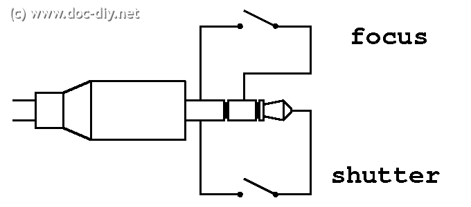